Geoscience Reference
In-Depth Information
B
C
A
D
G
E
F
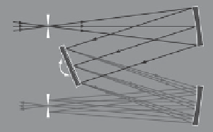
Figure 5.11. A Czerny-Turner monochromator. Light
(A)
is focused onto an entrance slit
(B)
and is
collimated by a curved mirror
(C)
. The collimated beam is diffracted from a rotatable grating
(D)
and
the dispersed beam refocused by a second mirror
(E)
at the exit slit
(F)
. Each wavelength of light is
focused to a different position at the slit, and the wavelength that is transmitted through the slit
(G)
depends on the rotation angle of the grating.(
http://upload.wikimedia.org/wikipedia/commons/e/e8/
angle
B
D
ν
β
α
angle
A
+
exit
slit
-
normal
entrance
slit
Figure 5.12. Graphical representation of the grating equation (Fortin,
2008
).
where
k
is the diffraction order,
n
the grating groove density (grooves per millimeter), and
λ
the vacuum wavelength in nanometers.
Equation (5.5)
illustrates the presence of overlapping spectral orders at a grating angle
but with higher diffraction orders. For example, if a signal is measured at 750 nm in the first
order then it is possible to also measure the light from 375 nm and 250 nm in their second
and third orders respectively. This is an important phenomenon that can be eliminated by
using either an additional dispersive element or a filter to separate or remove these orders
from the acquired signal. In addition, the diffraction order can be either positive or nega-
tive in direction (
www.newport.com
). In the case of a negative order the monochromator
can exhibit retro-diffraction effects that can also superimpose signals of the wrong spectral