Geoscience Reference
In-Depth Information
a
b
L
Almost
stationary
L
Slow
0
1
4
16
32
64
(mm/h)
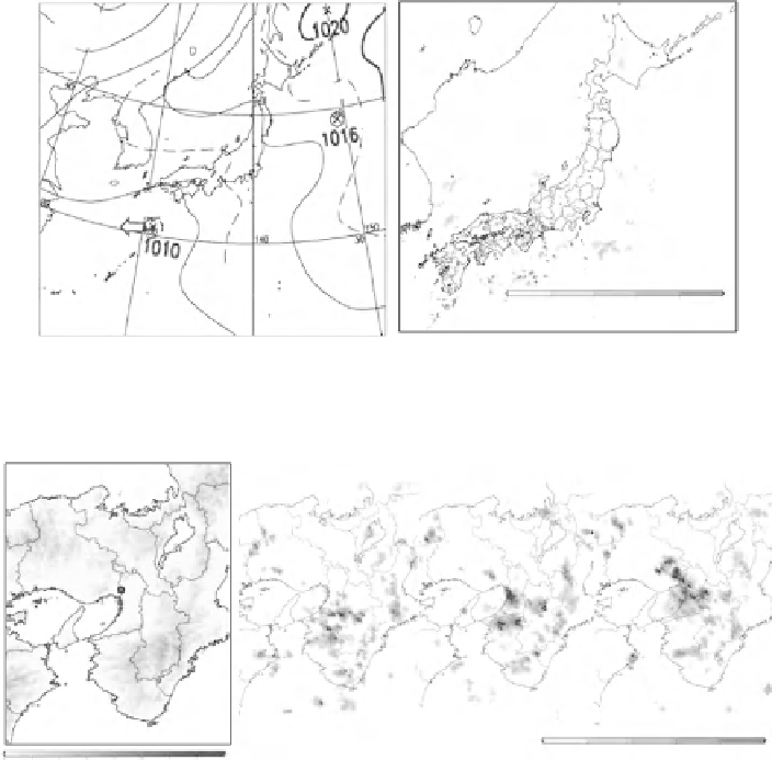
Fig. 20.1
(
a
) Surface weather chart at 15 JST 5th September 2008. (
b
) Rainfall distribution
observed by operational radars of JMA at 15 JST 5th September 2008
a
b
Osaka
International
Airport
Osaka
Plain
Kii-
Channel
Kansai
International
Airport
1400 JST
1500 JST
1600 JST
0
1
4
16
32
64
0
1000
2000
3000
4000
(mm/h)
(m)
Fig. 20.2
(
a
) Topography in and around the Osaka Plain. (
b
) Rainfall distribution observed by
operational radars of JMA from 1400 JST to 1600 JST 5th September 2008.
Circles
in (
b
) indicate
the rainfall regions generated in mountainous areas
20.3
Outlines of the Nested LETKF System
Figure
20.4
a shows the schematic illustration of the nested LETKF system. This
data assimilation system was composed of two LETKF systems: the Outer and
Inner LETKFs. The vertical layer structure was common in both LETKFs. Namely,
the number of vertical layers was 50 and the depth of the vertical layers was
increased from 40 to 880 m as the height increased. The height of the domain's top
was 22.6 km. The number of ensemble members was 12. Other parameters, such
as the horizontal grid interval, microphysical processes and so on depend on the
LETKFs.


Search WWH ::

Custom Search