Geoscience Reference
In-Depth Information
Fabry-Perot
Interferometer
water cooling
system
scattered light
Diode laser
DAC
X-ray
X-ray CCD
CO
2
laser
translation stage
for Brilouin optics
to T measurement
Spectrometer
with CCD
M
ND
Temperature
measurement
system
M
CF
M
BS
CCD
Laser heating
system
CO
2
laser
L
XRD
measurement
system
BS
Light
TV
monitor
ZSP
Light
M
M
M
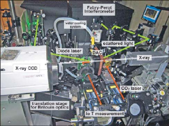
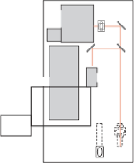
Fig. 6.2
Whole view of the Brillouin scattering
measurement system combined with
synchrotron X-ray diffraction and laser heating
systems at BL10XU of SPring-8 (a), and its
schematic layout (b) from Murakami
et al
.
(2009). Green, white and red lines indicate the
schematic optical paths for Brillouin scattering
measurements, X-ray diffraction and laser
heating system, respectively. Light green and
pale red lines indicate the scattered light and
transmitted light through the sample. SR,
synchrotron radiation; M, mirror; L, lens; BS,
beam splitter; BE, beam expander; ZSP, ZnSe
plate; PD, photodiode; DM, dichroic mirror; ID,
iris diaphragm; CF, color filter; VND, variable
ND filter; RP, retardation plate; RPF, rotational
polarized filter; MS, microscope. Reproduced
with permission of Elsevier.
Incident X-ray
Slit
L
L
Monochromator
Collimator
X-ray CCD
M
M
X-ray lenses
L
SR
ID
DAC
L
DM
ID
PD
ID
CCD
Focusing
assembly
M
M
ID
L
M
TV
monitor
M
M
Collecting
assembly
MS
ID
L
ID
RPF
VND
RP
M
M
ID
BS
M
CCD
Sandercock-type
tandem Fabry-Perot
interferometer
Diode-pumped
laser, 532 nm
Controller
TV
monitor
Brillouin scattering measurement system