Geoscience Reference
In-Depth Information
Because the beam from the antenna is not typically
pencil-narrow, a buried point reflector like a rock or a
landmine will provide a reflection even when not in the
(usually-vertical) boresight of the antenna. However, the
distance will be slightly larger when the reflector is off-axis,
and thus the reflection will map to a slightly greater depth.
As a result, point reflectors often appear as hyperbolic traces
in an echogram.
As with remote sensing radars, the choice of wavelength
is important. Longer wavelengths will typically penetrate
deeper before being attenuated, but demand physically
larger antennas for a given beamwidth. Long wavelengths
will be less sensitive to small reflectors like pebbles. Thus
the prudent researcher will visit a new site with a selection
of antennas, so that whatever is best for the project at hand,
and the conditions (notably, moisture, e.g., Bano and Girard
2001) can be chosen.
Probably the most significant findings from GPR studies
of dunes were those from one of the first applications of the
method—to the structure of the linear dunes in the Namib
(Bristow et al. 2000, 2005). These showed reflecting layers
consistent with the dune having migrated somewhat side-
ways, west-to-east, whereas of course the general sand
transport is along the south-north direction along the dune.
GPR studies have been made of booming dunes such as
suggested to be important in the booming process. Some
studies of Antarctic (Fig.
16.11
) and Alaskan dunes have
been reported, where snow, ice and water are important
factors in generating reflecting surfaces. Other studies
include those of dune/fluvial interaction in Australia (Hol-
lands et al. 2006) and of the internal structure of the Al-
godones dunes. The internal structure of a barchan is nicely
illustrated in Fig.
1.9
.
The reader will likely wonder whether the antenna needs
to be in contact with the ground. In principle, it need not
(and vehicle-mounted GPR systems a few tens of centi-
meters above the ground are used to detect landmines, for
example), but the signal-to-noise is vastly improved if it is,
and this need not preclude vehicular operation (Fig.
16.12
).
The analogy would be looking vertically into water on a
bright day with the sun overhead—it is much easier to see
the bottom by putting your face underwater than being
confronted with the glare from the air:water interface. The
air:sand gap similarly produces a major reflection which
challenges the dynamic range of the receiver. Airborne
radars are able to produce profiles of structures in terrestrial
ice sheets and glaciers (which if sufficiently cold and dry are
somewhat radar-transparent, like dry sand) but this relies on
the layers being detected having a separation rather larger
than the amplitude of the surface roughness within the beam
footprint. Such measurements have also been made by
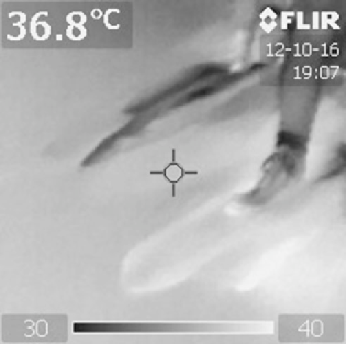
Fig. 16.7
Warmer and cooler avalanche lobes visible in a thermal
image at Sand Mountain, Nevada. Note the feet of two experimenters.
Photo R. Lorenz
(see Fig.
16.9
), this is probably the most accurate technique
(similar scanning has been used to quantitatively measure
the shape of ventifacts to measure erosion by saltating
sand), but involves a certain amount of bulky hardware and
an electrical generator. It seems that, for all but a few
applications, this scale of measurement may in the future be
performed mostly by photogrammetry.
16.2.5
Ground Penetrating Radar
Radar methods can measure distances with high precision—
this is after all the origin of the acronym Radio Detection
and Ranging. Thus the time-domain information of an echo
can reveal structure along the propagation direction of the
radar waves. This can be exploited to sound the structure
within a dune, if there are variations in dielectric constant
due to moisture, minerals or porosity. This approach is
termed ground-penetrating radar or GPR, and typically
involves an antenna on a sled (Fig.
16.10
) or cart, or
sometimes carried by hand (Fig.
10.11
). Radar pulses are
sent out directly into the ground and echoes received, the
echo time relating to the depth in the target via the speed of
light in sand. By traversing the antenna across the surface,
an image can be built up, with the horizontal coordinate
corresponding to the position of the antenna (estimated
from GPS, or sometimes from an odometer wheel on the
antenna), and the vertical to the depth. The brightness at
each point is estimated from the echo intensity.
Search WWH ::

Custom Search