Geoscience Reference
In-Depth Information
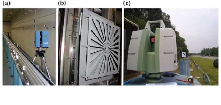
Fig. 3 Facilities and devices required for component calibration, calibration trackline (a), targets
with slots (b) and calibration baseline (c) (Brian et al.
2004
; Abbas et al.
2013
)
In this study, investigation of systematic errors was carried out by using point-
based self-calibration for the panoramic scanner (Faro Photon 120). Fifteen test
points were established using photogrammetry technique at the calibration field
and these points were used to evaluate the significant of self-calibration in
improving the accuracy. These test points then were used as the benchmark to
investigate the discrepancy obtained from TLS raw data and calibrated data, which
afterward indicates the reliability of calibration procedure for improving the
accuracy of TLS data.
2 Terrestrial Laser Scanner
Terrestrial laser scanner is a non-contact sensor, optics-based technology that
collects three-dimensional (3D) data of object surface automatically and in a
systematic pattern with a high data collecting rate. Compared to the traditional
approaches for the 3D measurement, TLS can be considered as combination of
photogrammetric and reflectorless total station. The scanning process within field
of view is similar to taking an image and data provided are similar to total station
(points in 3D coordinate system). Even though most of the commercial software
gives 3D data in Cartesian coordinates system (X, Y, Z). TLS actually measures
using spherical coordinates system r
;
u
;
ð Þ
and has intensity value as an attribute
(Fig.
4
). Therefore, the raw observables in TLS are (1) range (r); (2) horizontal
direction
ðÞ
; and (3) vertical angle
ðÞ
.
For further processing, especially for calibration purposes, 3D data in spherical
coordinate is more useful. Thus, conversion between Cartesian (x, y, z) and
spherical (range, horizontal direction and vertical angle) coordinates system can be
expressed as follows: