Geoscience Reference
In-Depth Information
are orientated perpendicularly to the surfaces over which
they act; they are thus normal stresses and the shear
stresses (
increasing values from left to right. Columns show increas-
ing values for the first subscript from top to bottom and
the same value for the second subscript.
In 3D, the state of stress at a point over a surface is
commonly represented by three mutually perpendicular
components: a normal stress and two shear stresses. In the
general case, the sum of the three components will result
in an inclined traction over the surface. To fully define the
state of stress at a point in a rock we need three normal
stresses and six shear stresses defined in three reciprocally
normal surfaces (Fig. 3.67a). With these nine components
it is possible to define the
stress tensor
, which is represented
in matrix form (see Appendix 1 for general information on
tensors). Each component is referenced to a coordinate
system
x, y, z
and, as in 2D, named by two subscripts. For
example, the normal stress acting over the horizontal plane
xy
, perpendicular to the axis
z
, is named
) here are zero. The surfaces, perpendicular to
the principal stresses, are called
principal planes of stress
.
For any other direction the corresponding traction is
inclined with respect to the surface and thus, has normal
and shear stresses acting.
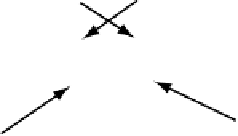
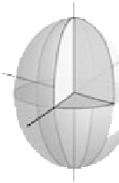
In 3D the stress tensor is an ellipsoid and the three axes
are the principal stresses:
1
is
the longest, major axis of the ellipsoid and represents the
traction with the biggest magnitude,
1
,
2
and
3
(Fig. 3.67).
2
has an intermedi-
ate value (which
does not
correspond to the mean stress
value) and
3
is the smallest. Two of the stresses may have
the same value:
1
2
3
.
Stresses are described in 2D by two normal stresses and
two shear stresses acting over two perpendicular surfaces
(Fig. 3.66). The values may be represented in a matrix
with four components. Rows in the matrix represent the
surface stress components acting over a particular surface.
Each component is referenced to a coordinate system
x,z
and named by two subscripts. The first subscript refers to
the axis
perpendicular
to the surface over which the force
is acting. The second refers to the
direction
of the traction
component. All of them share the same first subscript and
zz
and the two
shear components
zy
(Fig. 3.67a).
The principal diagonal, top-left to bottom-right is occu-
pied by normal stresses and the remaining positions by
shear stresses. It is important to note that in a state of equi-
librium, where torques are not allowed, only six of the
nine components are independent as the shear stresses act-
ing over adjacent surfaces have to be balanced such as
zx
and
(b)
(a)
z
s
zz
Principal stress vectors
z
s
xx
t
xz
t
yx
s
yy
t
yz
t
zx
t
zy
s
zz
t
xy
x
y
x
y
t
zx
t
zy
t
yz
t
xz
s
xx
t
xy
t
yx
s
1
0 0
0
s
2
0
0 0
s
3
s
yy
s
1
(c)
s
1
s
1
s
2
s
3
s
2
s
2
s
3
s
3
s
1
≥
s
2
≥
s
3
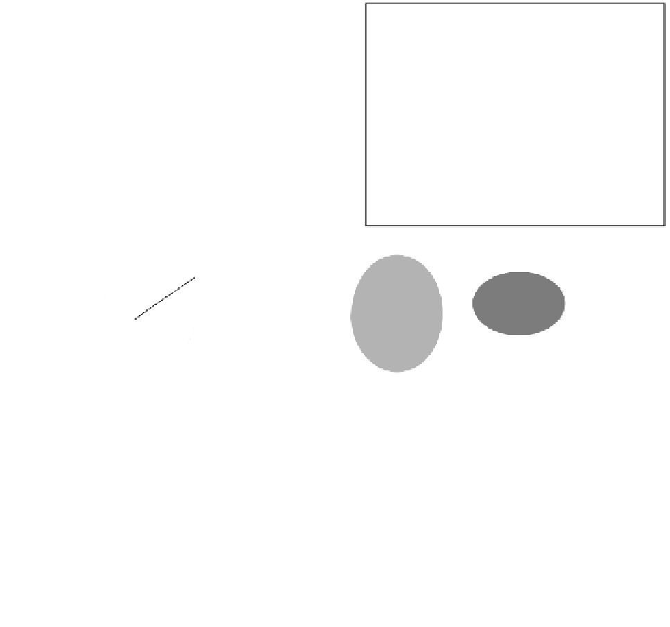
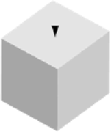
Fig. 3.67
(a) The stress state at a point centered in a small cube is defined by three normal stress components and six shear stress components.
(b) The principal stress vectors are normal stresses with shear stress values of 0. (c) The stress ellipsoid. Right: a 3D representations; Left: 2D
representations of the three principal planes of stress showing the corresponding main stresses and directions.


Search WWH ::

Custom Search