Geoscience Reference
In-Depth Information
shapes may considerably aid physical analysis. The grid is
built up by trial and error from an initial sketch of stream-
lines between the given boundaries. Then the equipoten-
tial lines are drawn so that their spacing is the same as the
streamline spacing. Continuous adjustments are made
until the grid is composed (as nearly as possible) of
squares, and the actual streamlines are then obtained. This is
useful because, for example, from the streamline construc-
tion one may deduce velocity and, with a knowledge of
Bernoulli's equation (Section 3.12), pressure variations.
However, it will be obvious to the reader that flow nets are
only a rather simple imitation of natural flow patterns.
Experimental studies will reveal patterns of flow that cannot
be guessed at by potential approaches (e.g. Fig. 2.19b).
2.5
Continuity: mass conservation of fluids
A fundamental principle in fluid flow is that of
conservation
,
the interaction between the physical parameters that deter-
mine mass between adjacent fluid streamlines. The trans-
port of mass,
m
, along a streamline involves the parameters
velocity,
u
, density,
to calculate the effects of decelerating or accelerating flow
(Section 3.2).
To be applicable, continuity of volume has important
conditions attached:
1
The fluid is incompressible, so no changes in density due to
this cause are allowed.
2
Fluid temperature is constant, so there is no thermally
induced change in density.
3
Fluid density due to salinity or suspended sediment con-
tent also remains unchanged.
4
No fluid is added, that is, there is no
source
, like a
submarine spring or oceanic upwelling.
5
No fluid is subtracted, that is, there is no
sink
, like a
permeable bounding layer or thirsty fish.
One natural environment where most of these condi-
tions are satisfied is a length of river channel, where cross-
sectional area changes downstream (e.g. Section 3.2).
, and volume,
V
. These determine the
conservation of mass discharge, termed
continuity
.
2.5.1
Continuity of volume with constant density
River, sea, and ocean environments essentially comprise
incompressible fluid. They contain layers, conduits, chan-
nels, or straits that vary in cross-sectional area,
a
, while a
discharge,
Q
(units L
3
T
1
) of the constant density fluid
through them remains steady, being supplied from else-
where due to a balance of applied forces at a constant rate
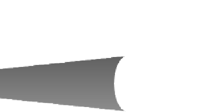
(Fig. 2.21). Generally, if there is cross-sectional area
a
1
and mean velocity
u
1
upstream, and area
a
2
and mean
velocity
u
2
downstream, the product
Q
u
a
must remain
constant (you can check that the product
Q
has dimen-
sions of discharge, or flux, L
3
T
1
). We then have the
equality
u
1
a
1
2.5.2
Continuity of mass with variable density
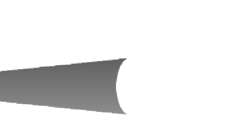
Consider now a steady discharge of fluid with a variable
density that flows into, through, and out of any fixed vol-
ume containing mass,
m
(Fig. 2.22). If that mass changes
then the difference,
u
2
a
2
so that any change in cross-sectional
area is accompanied by an increase or decrease of mean
velocity and there is no change in
Q
that is,
0. Any
changes in
u
naturally result in acceleration or decelera-
tion. This simplest possible statement of the continuity
equation may be used in very many natural environments
Q
m
, may be due to a change of fluid
density,
, of the fluid within the volume over time
and/or space. The fact that density is now free to vary, as
a
= area
a
2
>
a
1
r
= constant
Q
1
=
Q
2
=
a
1
u
1
=
a
2
u
2
u
1
>
u
2
a
= area
a
2
>
a
1
r
= variable
m
1
=
m
2
=
a
1
r
1
u
1
=
a
2
r
2
u
2
a
1
a
1
Q
2
r
2
r
1
m
1
u
1
u
2
u
2
u
1
a
2
a
2
Q
1
Fig. 2.21
Continuity of volume: constant density case in 1D.
Fig. 2.22
Continuity of mass: variable density case in 1D.


Search WWH ::

Custom Search