Geoscience Reference
In-Depth Information
z
T
2
>T
1
Vertical slot
δ
d
(d) Horizontal slot
T
w
T
1
T
∆
T
d
T
o
T
2
∆
T
T
1
h
T
2
l
w
Side
view
Fluid
reservoir
at
T
o
Counter-rotating cells at
Ra
>
c
.1,700
w = 0
(e) Horizontal reservoir
T
1
Free
surface
∆
T
T
2
Thermal boundary layer
thickness,
d
,
temperature,
T
, velocity,
w
.
Side
view
(a)
single
cell
(b)
multiple
cells
(c)
turbulent
cell
y
Plan
view
Fig. 4.151
Development of a free convective thermal boundary layer
in a wide fluid reservoir adjacent to a vertical heated wall.
> Rayleigh No.
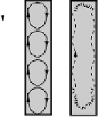
Fig. 4.152
Convection in vertical slots and in horizontal slots and
reservoirs.
density, and when the buoyancy force exceeds the resisting
force due to viscosity it moves upward along the wall at
constant velocity, with the overall negative buoyancy force
in balance with pressure and viscous forces. At this time,
the background heat being continuously transferred across
the wall by conduction, a portion is now transporting
upward by convection within a thin
thermal boundary
layer
. The general form of the boundary layer and of the
temperature and velocity gradients across it are illustrated
in Fig. 4.151. This situation encourages us to think about
the possible controls upon convection and upon the
nature of the associated boundary layers, for it must be the
balance between a fluid's viscosity and thermal diffusivity
that controls the degree and rate of conduction versus
convection of heat energy and therefore the rate of trans-
fer of temperature and velocity. We might imagine that
when the viscosity: diffusivity ratio is high then the veloc-
ity boundary layer is thick compared to the temperature
one, vice versa for a low ratio. In detail the prediction of
boundary layer properties depends critically upon whether
the flows are laminar or turbulent, hence the consideration
of a thermal equivalent to
Re
.
The foregoing analysis has been rather dry and a little
abstract and does scant justice to the interesting patterns
and scales of free convection. That the process is hardly
predictable and achievable by molecular scale motions is
illustrated by the great variety of natural thunderclouds or
by laboratory flow visualizations. Once heated or cooled
by conduction the moving fluid takes on extraordinary
forms. We illustrate convective flows within vertical or hor-
izontal wall-bounded slots and in open containers
(Fig. 4.152). Here the convection takes the form of single
(Fig. 4.152a) or multiple (Fig. 4.152b) vertical cells, tur-
bulent vertical cells (Fig. 4.152c), nested counter rotating
cells seen as polygons in plan view (Figs 4.152d, e and
4.153) or multiple parallel convective cells or rolls that
adjust to both the shape of the containing walls and the
presence of a free surface (Figs 4.154 and 4.155). The
polygonal convective cells may form under the influence of
variations in surface tension caused by warming and cooling
and are termed Bérnard convection cells. Perhaps the com-
monest form of convection in nature involves the heating of
a fluid by a point, line, or wall source to produce laminar or
turbulent
thermal plumes
(Figs 4.156 and 4.159). Such
plumes play an important role in the vertical transport of
heat in the Earth's mantle, oceans, and atmosphere.
4.20.4
Forced convection through a boundary layer
In forced convection, the motive force for fluid movement
comes from some external source; the fluid is forced to
transfer heat as it flows over a surface kept at a higher


Search WWH ::

Custom Search