Geoscience Reference
In-Depth Information
the
shear modulus, G
, and the density of the substances
that they pass through. We have seen (Section 3.15) that
the bulk modulus relates the change in hydrostatic pres-
sure,
P
, in a block of isotropic material to the change in
volume,
V
, that is,
K
Layer 1
Speed
u
1
Reflected
ray
i
i
u
2
>
u
1
d
P
/d
V
. Both solids and fluids are
compressible and hence both can sustain
P
- and
S
-waves.
The shear modulus is the ratio between the shear stress,
Refracted
ray
Layer 2
Speed
u
2
r
,
and the shear strain,
, in a cube of isotropic material sub-
jected to simple shear, that is,
G
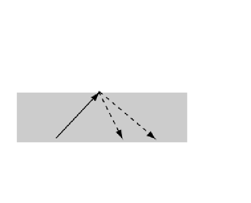
Snell´s laws: 1. reflection angle,
i
, equals
incident angle,
i
2. refraction angle,
r
, and incident angle,
i
are related by: sin
i
/
u
1
= sin
r
/
u
2
.
G
is thus a meas-
ure of the resistance to deformation by shear stress, in a
way equivalent to the viscosity in fluids. Since fluids like air
and water cannot support shear motions by finite strain,
G
is zero and hence
S
-waves cannot travel through them.
The expressions for wave speeds (Box 4.2) are rather sur-
prising in that they depend inversely upon density and
since we think that this property of rocks generally
increases with depth it might imply that seismic wave
speeds decrease with depth in the earth. However the
values of
K
and
G
both depend to a large degree upon
density and increase more rapidly with depth than density
does (Box 4.2; compare with estimates from Oldham's
original data given in Fig. 4.130), giving the required
/
Fig. 4.134
Seismic reflection from an interface (like the
MOHO
) and
refraction across it.
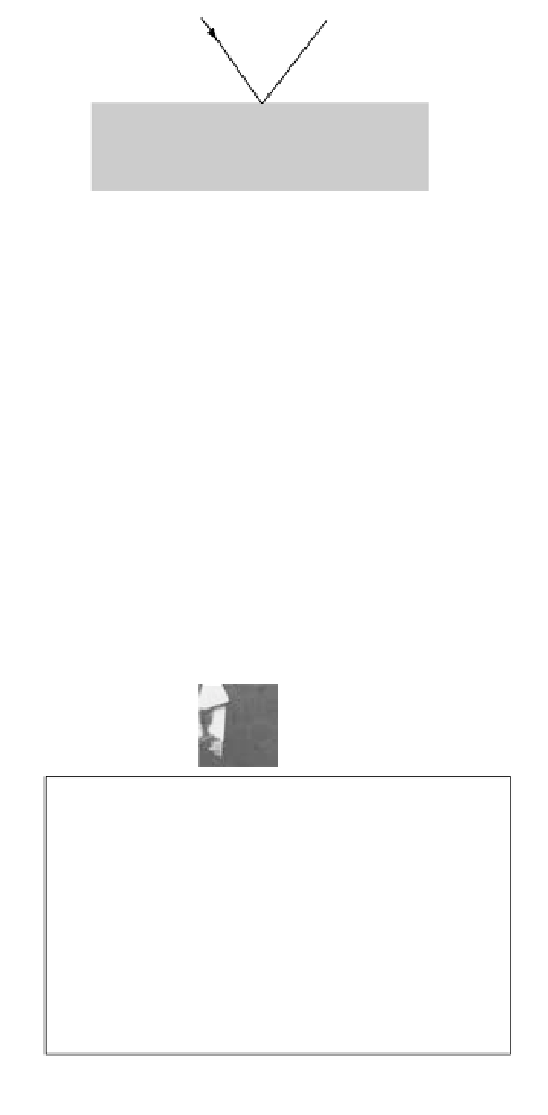
There is a critical angle,
i
c
that enables refraction at
r
Reflected
= 90
o
and hence a wave
path along the interface
to observer at
x
S
2
P
Mohorovicic
Layer 1
x
1
x
2
F
Layer 2
Layer 1
Speed
u
i
c
P
1
P
S
i
c
i
r
Refracted
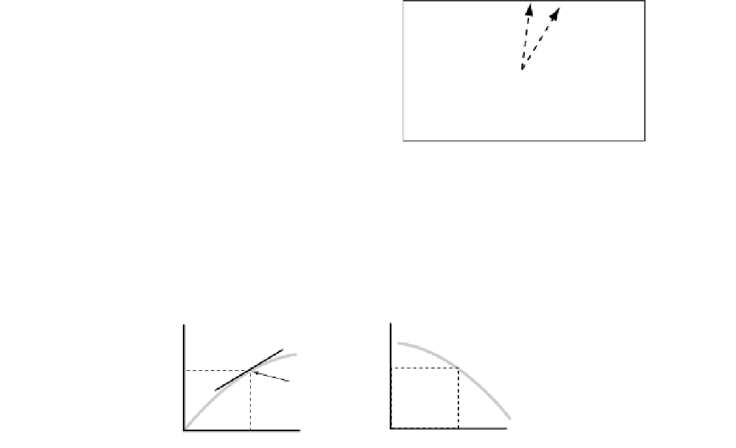
Any obliquely incident body wave
may generate both refracted and
reflected P
and
S waves from a layer
density discontinuity.
Layer 2
Speed
u
2
Fig. 4.136
Incident body waves generate a variety of reflected and
refracted phases.
Fig. 4.135
Critical seismic refraction across an interface like the
MOHO.
KNOWN
for shaded seismic raypath,
T
=
f
(
∆
)
UNKNOWN
for given seismic raypath,
v
=
f
(
r
)
B
A
At B, Velocity is
v
1
At depth (
r
0
-
r
1
)
v
1
T
1
At A,
dT
/
d
∆
= p
1
r
0
= radius
r
1
, Radial depth
∆
1
Arc distance
Fig. 4.137
The seismic “inverse problem.”


Search WWH ::

Custom Search