Geoscience Reference
In-Depth Information
(a)
(b)
t
t
Effective
stress
Applied
stress
Applied
stress
2
u
= 180º
2
u
f
= 120º
s
n
s
1
Ε
s
n
Ε
s
1
Ε
s
3
=
T
0
s
3
Ε
s
3
Ε
s
1
s
3
s
1
s
n
s
n
2
u
f
= -120º
Effective
stress
P
f
Stable field
P
f
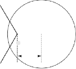
Fig. 4.91
Effect of pore fluid pressure in fracture formation. (a) With high differential stresses Coulomb fractures can be produced when the
Mohr circle moves to the left by pore fluid pressure. (b) With low differential stresses, even when the applied stress may be compressive, and
fully located in the field of stress stability, fluid pore pressure can reduce the effective stress displacing the circle to the tensile field and
producing joints if the condition
E
3
T
0
is satisfied.
to a lower level, while maintaining the differential
stress(Fig. 4.91). With low differential stresses, even when
the applied stress may be compressive, and fully located in
the field of stress stability, fluid pore pressure can reduce
the effective stress displacing the circle to the tensile field
and producing joints if the condition
˜
3
T
0
is satisfied.
E
4.15
Faults
4.15.1
Nomenclature and orientation
Faults are fracture surfaces or zones where several adjacent
fractures form a narrow band along which a significant
shear displacement has taken place (Fig. 4.92a, b).
Although faults are often described as signifying brittle
deformation there is a transition to ductile behavior where
shear zones develop instead. As described in Section 4.14,
shear zones show intense deformation along a narrow band
where cohesive loss takes place on limited, discontinuous
surfaces (Fig. 4.92c). Faults are commonly regarded as large
shear fractures, though the boundary between features
properly regarded as
shear fractures
or joints is not sharply
established. In any case, although millimeter-scale shear
fractures are called
microfaults
, faults may range in length of
order several decimeter to hundreds of kilometers: they can
be localized features or of lithospheric scale defining plate
boundaries (Section 5.2). Displacements are generally con-
spicuous (Fig. 4.93), and can vary from 10
3
m in hand
specimens or outcrop scale to 10
5
m at regional or global
scales. Faults can be recognized in several ways indicating
shear displacement, either by the presence of scarps in recent
faults (Fig. 4.93a and b), offsets, displacements, gaps, or
overlaps of rock masses with identifiable aspects on them
such as bedding, layering, etc. (Fig. 4.93c).
Fault nomenclature is often unclear, coming from widely
different sources. For example, quite a lot of the terms
used to describe faults comes from old mining usage, even
the term
fault
itself, and the terms are not always well con-
strained. Fault surfaces can be inclined at different angles
and their orientation is given, as any other geological sur-
face, by the
strike
and
dip
(Fig. 4.94a). A first division is
made according to the fault dip angle;
high-angle faults
are
those dipping more than 45
and
low-angle faults
are those
dipping less than 45
. Faults divide rocks in two offset
blocks at either side of the fracture surface. If the fault is
inclined, the block which is resting over the fault surface is
named the hanging wall block (HWB, Fig. 4.95) and its
corresponding surface the
hanging wall
(HW, Fig. 4.96);
and the underlying block which supports the weight of the
hanging wall is called the footwall block (FWB, Fig. 4.95);
the corresponding fault surface is called the
footwall
(FW,
Fig. 4.96). If homologous points previous to fracturing at
each side of the fault can be recognized, the reconstruc-
tion of the relative displacement vector or slip can be
reconstructed over the fault surface, both in magnitude


Search WWH ::

Custom Search