Geoscience Reference
In-Depth Information
(a)
Tension
Compression
t
Linear
relation
(c)
Tension
Compression
t
s
n
Stress state
stable
s
n
,
t
2
u
Stress state
not possible
s
n
s
3
s
1
2
u
(b)
Tension
Compression
t
Nonlinear
relation
s
n
Stress state
not possible
Fig. 4.81
Fracture criteria. (a) General graphic representation of a linear fracture criterion. The failure envelope at which fractures occur, sepa-
rates a field of stable stresses (white) from a field of unstable stresses (shaded), where states of stress are not possible (unstable stress) because
rock strength is exceeded. (b) Nonlinear parabolic fracture criterion showing the same fields as before. (c) Mohr circle showing the angles
(both for positive and negative shear) at which fractures form (
is the angle that the fracture surface forms with the normal to
1
).
surface forms respect to
1
(Fig. 4.82). Fracture angle
with the principal stress
1
can be calculated as
90
. Linear fracture criteria predict that fracture angles
with respect to the main stresses remain constant for all the
experiments, whereas in nonlinear criteria the angles
should vary along the curve.
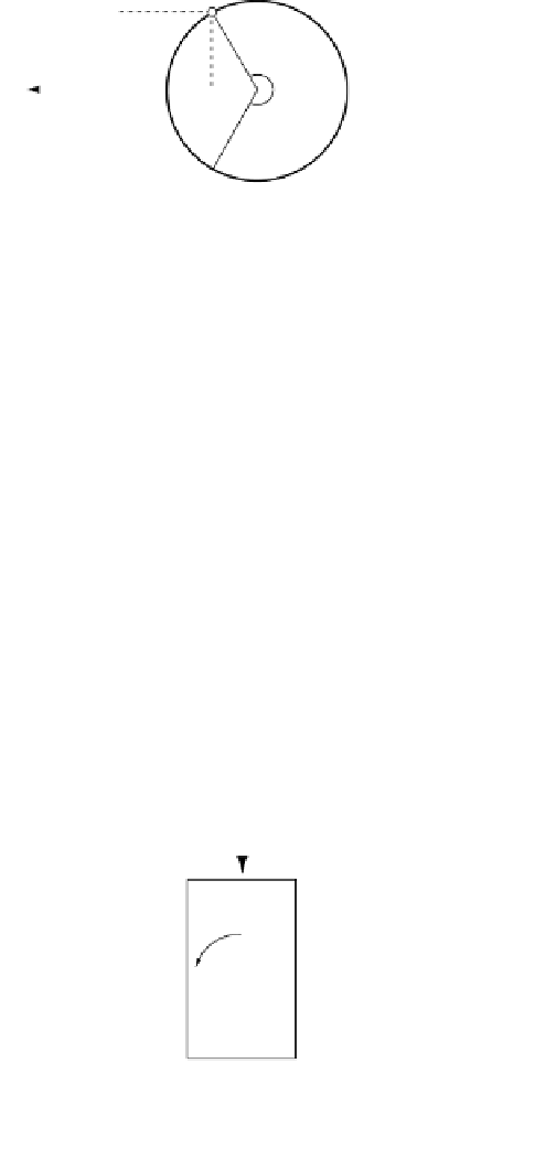
Several kinds of fractures can be produced in different
situations (Fig. 4.83). In tests of uniaxial extension, which
are carried out by stretching the sample from the long axis,
without lateral confinement (
s
1
Fracture
surface
Normal to
the fracture
surface
a
u
u
Normal to
s
1
0; Fig. 4.83a)
tensile fractures are formed. Axial compression tests
are established by applying an axial load, which defines the
main principal stress
1
2
a
1
, in unconfined conditions
(
0; Fig. 4.83b); this will cause vertical splitting
of the sample, with fractures orientated parallel to the
main applied load. Axial or triaxial settings, in which
compression is carried out with some level of confining
2
3
s
1
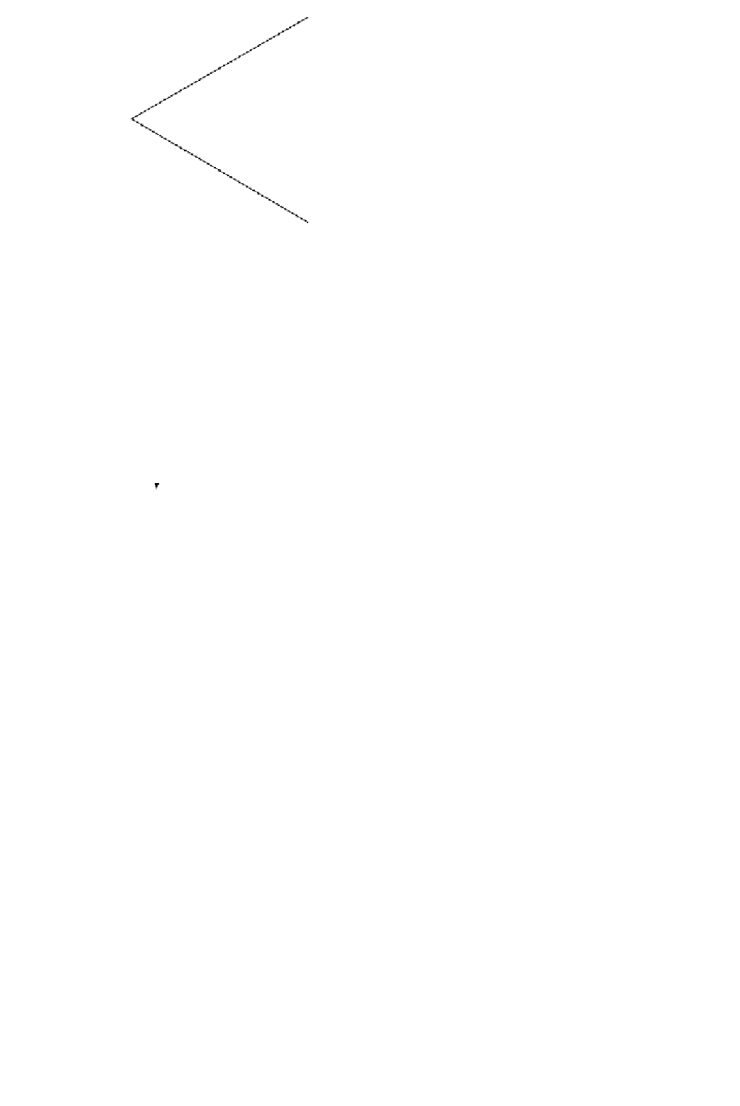
Fig. 4.82
Geometric relation between the angle
and the fracture
angle
, which is the angle between
1
and the fracture surface.


Search WWH ::

Custom Search