Geoscience Reference
In-Depth Information
absolutely featureless,
slickenlines, striations
, or
ridge and
groove lineations
can be observed, reflecting the shear move-
ment of the blocks parallel to the fracture surface. Acicular
crystal fibers or slickenfibers, resulting from crystal growth
in the shear direction under stress, are also common. Shear
fractures can form as two conjugate sets forming an angle of
approximately 30
s
1
s
2
with respect to the principal stress surface
containing
2
, which bisects the angle between the
two fracture sets (Fig. 4.77). Shear fractures can be associ-
ated with faults (Section 4.15) as minor features, having the
same orientation and origin as the faults.
1
and
s
3
4.14.4
Fracture mechanics
A great deal of knowledge concerning fracture mechanics
comes from laboratory experiments. We discussed briefly
in Section 3.15 the importance of experiments in the lab
to observe stress-strain relations in rheology. The impor-
tant field of interest in rheology is how rocks behave when
subjected to stresses under certain controlled conditions of
pressure, temperature, presence of fluids, etc. In this chap-
ter we focus on the particular relation between stress and
fracture formation. It is of particular interest how and why
rocks break when differential stresses reach the critical
value of rock resistance at the elastic or plastic limit and
consequently break. Also it is important to observe under
which conditions different kinds of fractures form and
which are the fracture angles in relation to applied stresses.
This field of knowledge, dealing with fracture or rock
mechanics is very important in many applied fields, as in
civil engineering, mining, and hazard controls (rock and
soil stability in slopes, both natural and constructed). It
has been developed over the years by both structural geol-
ogists and engineers, with mathematical models and frac-
ture criteria of increasing accuracy.
To carry out fracture experiments, samples of different
lithologies are cut using a special drilling device and
smoothed at the surfaces to avoid irregularities that can
cause unwanted, inhomogeneous stress concentrations.
Rock samples as isotropic and homogeneous as possible
are preferred. Samples are generally cylindrical, several
centimeters in diameter with a length of about four or five
times this amount. Both dimensions have to be measured
accurately before making the experiment. Several tests can
be made both by pulling apart or compressing the samples,
as in the dog-bone specimens (Fig. 4.79a, b) and the
Brazilian discs pressed down to achieve a perpendicular
tension (Fig. 4.79c). A number of diverse apparatuses have
been designed to carry out different tests which can be
made in unconfined conditions or with lateral confinement
Fig. 4.77
Relations between two conjugate shear fractures and the
related extension fractures formed under the same stress system. The
principal compressive stresses and the shear movement are shown.
(a)
(b)
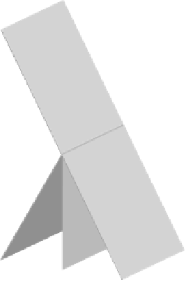
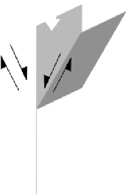
Fig. 4.78
Shear zones: (a) Conjugate brittle shear fractures and
associated feather joints. (b) Conjugate shear zones at the brittle-
ductile transition, showing two generations of gash veins. Note the
orientation of extension and shear fractures as in Fig. 27.8.
fracture is generally used for joint-scale fractures showing
discrete block displacements and which sometimes are not
even discernible at outcrop scale. Some of these fractures
consist of joints that experience some sliding of blocks after
being formed as extension fractures, due to tectonic reacti-
vation or simply small geometric adjustments. Shear frac-
tures appear as smooth well-defined planes which may be
arranged systematically as joints with regular spacing and
with similar trends. Although shear fracture surfaces can be


Search WWH ::

Custom Search