Geoscience Reference
In-Depth Information
S
1
S
1
S
3
S
3
S
3
S
1
S
1
S
3
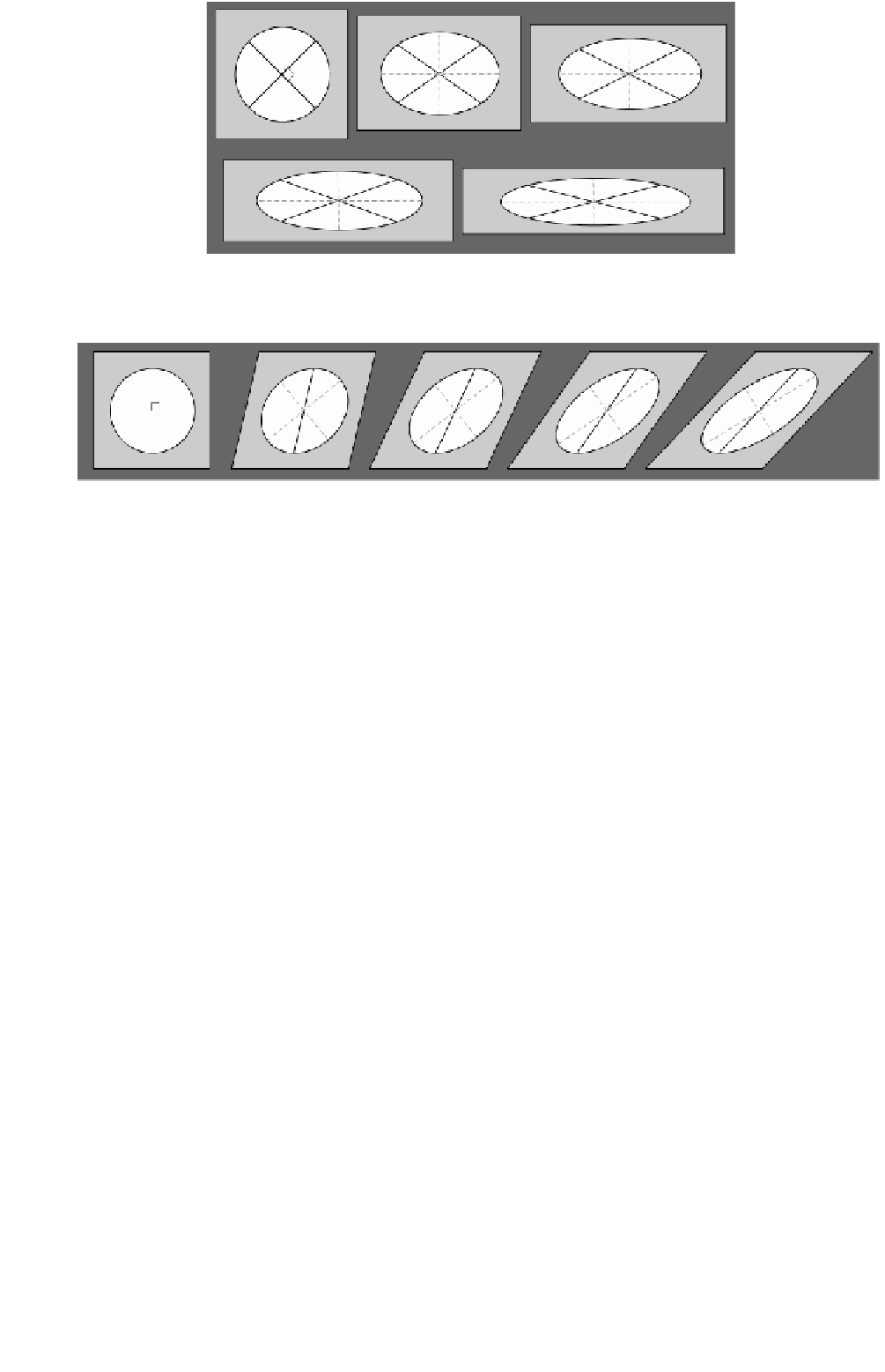
Fig. 3.88
Pure shear is considered to be a coaxial strain since the orientation of the axes of the strain ellipse
S
1
and
S
3
remain with the same
orientation through progressively more deformed situations.
S
3
S
3
S
1
S
1
S
1
S
1
r
= 1
S
3
S
3
Fig. 3.89
Simple shear can be described as a noncoaxial strain as the orientation of the principal strain axis of the strain ellipse
S
1
and
S
3
rotates
with progressive steps on deformation.
and so the strain is
noncoaxial
. The orientation of the axes
is not maintained, which means that the directions of max-
imum and minimum extension rotate progressively with
time.
After deformation, the circle has suffered strain and devel-
oped into a perfect ellipse by homogeneous flattening
(Fig. 3.90b). The original radius
R
of the circle, with
length
l
0
, has been elongated and will correspond to the
radius
R
of the ellipse of length
l
1
. Comparing both
lengths, the extension,
e
(Equation 1; Fig. 3.81) or the
stretch,
S
(Equation 2; Fig. 3.81), can be easily calculated.
The reciprocal quadratic elongation can be directly
obtained as
3.14.7 The fundamental strain equations and
the Mohr circles for strain
(
l
0
/
l
1
)
2
. The angular deformation can be
measured by plotting the tangent to the ellipse at the point
p
, where the radius intercepts the ellipse perimeter, then
plotting the normal to the tangent, and measuring the
angle with respect to the radius
R
For any strained body the shear strain and the stretch can
be calculated for any line forming an angle
with respect
to the principal strain axis
S
1
if the orientation and values
of
S
1
and
S
3
are known. As in the case of stress analysis
the approach can be taken in 2D or 3D. Although it is
important to remember that the physical meanings of
strain and stress are completely different, the equations
have the same mathematical form (Fig. 3.90) and can be
derived using a similar approach. The fundamental strain
equations allow the calculation of changes in length of
lines, defined by means of the
reciprocal quadratic elonga-
tion(
(Fig. 3.90b).
The Mohr circle strain diagram is a useful tool to graph-
ically represent and calculate strain parameters, following a
similar procedure that was used to calculate stress compo-
nents. In this case the ratio between the shear strain and the
quadratic elongation (
) is represented on the vertical
axis and the reciprocal quadratic elongation (
/
) on the
horizontal axis (Fig. 3.90c). The
ratio is an index of
the relative importance of the angular deformation
versus
the linear elongation. When the ratio is very small, changes
in length dominate, in fact when the ratio equals zero,
there is no shear strain, which coincides with the directions
of the principal strain axis. In homogeneous strain of pure
/
with
respect to the direction of maximum stretch
S
1
. To illus-
trate the use and significance of the Mohr circles for strain,
an original circle of radius
R
can be used (as in Fig. 3.87).
1/
)
, of any line forming an angle

Search WWH ::

Custom Search