Geoscience Reference
In-Depth Information
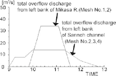
Fig. 5.
Inflow discharge hydrographs.
Fig. 6.
Inflow imposed meshes.
As for the boundary condition, the overflow discharge from the Mikasa
River obtained by Hashimoto
et al.
4
is imposed. Figure 5 shows the dis-
charge hydrograph and Fig. 6 shows the storage ponds to which the overflow
discharge is allocated as the lateral inflow. The computation start time is
9:00 on June 29, 1999, when the overflow began from Sannoh channel.
In the computation, the drainage by sewerage system of 36.4 mm/h, 70%
of the designed value is considered. The inflow water into the basements of
buildings and the water stored in the storage tank of the underground mall
are also considered. Steps of entrance to underground space and pavement
(30 cm high in total) are also taken into account.
The values of Manning coecient,
n
, are 0.067 for ground and 0.03 for
underground, respectively, and the discharge coecient of drop formula is
0.544. The computational time step ∆
t
is set to be 0.05 s.