Geoscience Reference
In-Depth Information
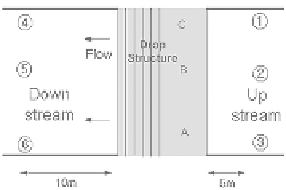
Fig. 2.
Plan and measuring points at the drop structure.
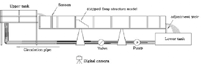
Fig. 3.
Experimental arrangement.
parameters of the stepped drop structure, the experimental tests were per-
formed. Figure 3 shows the experimental arrangements. The typical model
of the stepped drop structure made of waterproof plywood was installed
in a recirculatory tilting flume of 0.4 m wide, 0.4 m deep and 15 m long.
The sidewall of the flume was made of glass and a transparent scale was
attached to the side wall to see the flow features well. A damper was laid
at the upstream section of the flume to reduce the turbulence and to assure
the hydraulic feed having negligible kinetic components. Water level was
regulated by the down-stream adjustment weir. The discharge which was
controlled by a valve in a feedback loop could be measured with a v-notch
at the upper tank.
The stepped drop model was 0.4 m wide and 0.31 m high, and five dif-
ferent slopes were selected (1:2.0, 1:1.7, 1:1.5, 1:1.2, and 1:0.7). Hence, in
case of the drop model 1:2.0, the model was 0.4 m wide, 0.54 m long, 0.31 m
high and on a slope of 30
◦
. The number of steps was 12, each step was
0.4 m wide, 0.09 m long and 0.052 m high. Flow velocity was measured by
using an electromagnetic current meter (model; MI-ECM4). To check the