Geoscience Reference
In-Depth Information
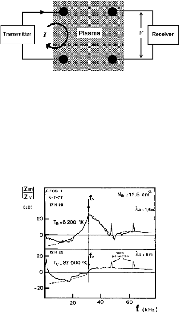
Fig. 1.
A schematic illustration showing how the mutual impedance
Z
=
V/I
of a
quadripole probe is determined.
ones, potential difference
V
, on open circuit, is independent of perturba-
tions (ion sheaths). The transmitter-receiver distance has thus to be larger
than twice the plasma Debye length. The antennae are nevertheless short
compared with the wavelength of EM waves so that the quasi-static approx-
imation applies. Both imaginary and real parts of
Z
may then be interpreted
to deduce plasma properties. Typical responses of the mutual impedance
probe as a function of frequency for two Debye lengths (1.6 m above and
6 m below) and a plasma density of 11.5 cm
−
3
are shown in Fig. 2. Solid
lines refer to the modulus of
Z
normalized to its value in vacuum. Dotted
Fig. 2. Typical mutual impedance frequency responses measured onboard GEOS-1 for
a plasma density of 11.5 cm
−
3
and two Debye lengths, 1.6 m (
top
)and6m(
bottom
).
5