Geoscience Reference
In-Depth Information
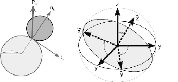
Fig. 13.1. Contact normal
n
k
,tangential direction
t
k
and contact force
P
k
defined at
particlecontact (left)and virtual plane of twodimensional shear mechanism defined by
local coordinate indicated by the broken line vectors (right)(Iai and Ozutsumi, 2005)
normal that are parallel to a plane (Iai, 1993). Assemblage of those pairs constitutes a
two dimensional mechanism and hereafter called “virtual two dimensional mechanism.”
In order to identify the structure of the virtual two dimensional mechanism, the local
coordinates
y
axis parallel
to the
x
-
y
plane of the reference frame that is defined by the coordinates
x
x
˜
,
˜
y
,
˜
z
areintroduced bytaking
˜
z
axis normal to theplane and
˜
,
y
,
z
(see
Figure 13.1, right).
Thesecondlevelofstructuresisidentifiedwithinthevirtualtwodimensionalmechanism
bysystematicallygroupingthecontactsaccordingtotheorientationrelativeto
x
axis.For
˜
convenience,theorientationrangingfrom0to
π/
2relativeto
x
axisisdividedinto
I
sets
˜
of zones, each ranging from
(ω
i
−
ω/
2
)/
2to
(ω
i
+
ω/
2
)/
2for
i
=
1
,...,
I
, where
ω
i
=
(
i
−
1
)ω
(13.3)
ω
=
π/
I
(13.4)
n
(
i
k
is taken in the plane as a representative direction with an angle
Contact normal
˜
ω
i
/
2
relative to
x
axis. By systematically identifying and combining the couples of contacts
that have the contact normals perpendicular to each other, the structure of the stress
contribution
˜
σ
kl
from the virtual two dimensional mechanism is identified as follows
(Iai, 1993):
I
q
(
i
)
F
n
(
i
)
k
n
(
i
)
l
q
(
i
)
S
t
(
i
)
k
n
(
i
)
l
σ
kl
=˜
p
δ
kl
+
˜
˜
,
˜
+˜
,
˜
ω
(13.5)
i
=
1
where
δ
ij
denotes Kronecker deltaand
n
(
i
)
k
n
(
i
)
l
n
(
i
)
k
n
(
i
)
l
n
(
i
+
I
)
k
n
(
i
+
I
)
l
˜
,
˜
=˜
˜
−˜
˜
(13.6)
t
(
i
)
k
n
(
i
)
l
=
t
(
i
)
k
n
(
i
)
l
−
t
(
i
+
I
)
k
n
(
i
+
I
)
l
=
t
(
i
)
k
n
(
i
)
l
n
(
i
)
k
t
(
i
)
l
,
˜
˜
˜
˜
+˜
(13.7)