Geoscience Reference
In-Depth Information
3. Stressstatesin soil and itseffect on sub-grade reaction development.
4. Deformation and failuremode of pilefoundations under near prototype scale.
To investigate inertial and kinematic effects on failure and deformation mode of piles
duringthree-dimensionalshaking,physicalmodetestswereconducted(TabataandSato,
2006). A 3
3 steel pile group (each pile had a diameter of 152.4mm and a wall thick-
nessof2.0mm)supportingafoundationwithorwithoutasuperstructurewassetinadry
sand deposit prepared in a cylindrical laminar box with a height of 6.5m and a radius of
8.0m (Figure 5.26). The piles were set up with a horizontal space of four-pile diameters
centretocentre.Theirtipswerejointedtothelaminarboxbasewithpinsandtheirheads
were fixed to the foundation of a weight of 10 tons. Experimental variables included the
natural period of the superstructure and the presence of foundation. Many strain gauges,
accelerometers, velocity metre, earth pressure transducers displacement transducers, set-
tlement metres and load cells, about 900 sensors in total, were placed in the deposit
as well as on the pile-structure model. The tests were conducted under one-, two- or
three-dimensional shaking with three types of ground motion having a peak acceleration
adjusted from0
×
s
2
to 8
s
2
.
.
3m
/
.
0m
/
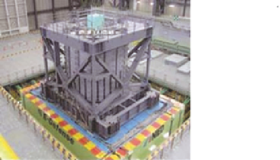
Figure 5.26 shows a test model constructed in a cylindrical laminar box, 150 tons in
total with a height of 6.5m and a radius of 8.0m, placed on the large shaking table.
Thecylindricallaminarboxconsistsof41ringflames,enablingsheardeformationofthe
insidesoilduringtwo-dimensionalhorizontalshaking.Thetotalweightofthetestmodel
excluding the cylindrical laminar box and its attachments was 750 tons. After setting the
pilegroupinthelaminarbox,thesandwasplacedarelativedensityofabout70%toform
a uniform deposit with a thickness of 6.3m. A total of five test series were conducted, in
which the presence of foundation embedment and superstructure, and the natural period
of the superstructure, as well as the type of input motions, and their components and
maximum acceleration were varied (Tokimatsu et al.,2007).
1.6m
N
WE
S
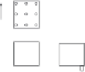
Plan view of pile group
Superstructure
D, E
A, B
Column
Foundation
0.3m
1.0m
0.5m
0.6m
8.0m
Elevation of soil-pile-structure model
Fig. 5.26. Testlayout inlaminar container mounted onthe E-Defense Shake table