Geoscience Reference
In-Depth Information
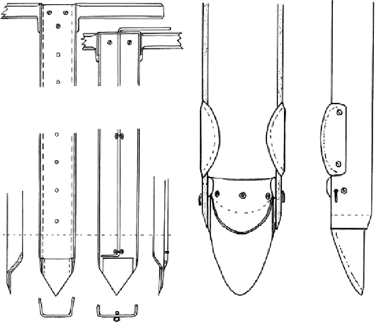
Figure 2.16
Plan and side view showing the end of the second half to be driven; the main blade,
attached to the inside circumference of the plastic tube, has two flanges that internally
slightly overlap the first half to be driven (
after
Seaby, 2001).
this blade is a loop of spring steel wire, which, due to its hinging through holes in the
outer edges of the blade, is pushed against its inside circumference during insertion;
during extraction, a slight downward movement, relative to the sampler, swings it out
to help grip the core firmly. To align the two halves during insertion the second half
has wider cutting blades, one attached to each side near the tip. These closely overlap
the first half externally, acting as a guide. Both halves have cross handles near the top,
but to aid extraction and reduce the risk of back strain, the halves are bolted together
and a series of holes along one length allows a lever with a pointed tip, acting over a
fulcrum, to ease the sampler out.
Deformation of soil during sampling causes disturbance of the soil sample. The
volume displacement can be minimized by adjusting the area ratio (the ratio of the
external to the internal diameter of the sampler). An optimal combination of area ratio
and angle of cutting edges is essential for better quality sampling. A good sampler for
low- to high-fibrous peat should ideally have good cutting edges and excellent driving
technique to collect high-quality samples with different dimensions while keeping the
sampling cost low (Al-Raziqi
et al.
, 2003).