Geoscience Reference
In-Depth Information
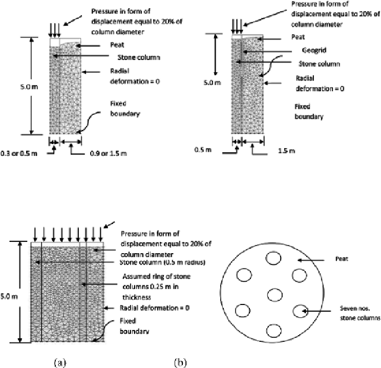
Figure 7.41
Deformed mesh for SC and GC,
s
/
d
=
3,
c
=
6 kPa, diameter
=
1.0m, geogrid up to 3
d
:
(a) deformed mesh for column area only loaded for SC; (b) deformed mesh for column
area alone loaded for GC (
after
Prasad
et al.
, 2012).
Figure 7.42
(a) Deformed mesh, entire area loaded, group of seven columns (SC),
s
/
d
=
3,
c
=
6 kPa,
diameter
=
1.0m; (b) plan view of the group layout (
after
Prasad
et al.
, 2012).
observed that the failure is by bulging of the column at a depth about 0.5 to 2.0 times
the diameter of the column (Figure 7.41(a)). The bulging disappears when the column
is encased with geogrid as seen in Figure 7.41(b).
A typical deformed mesh for the group of seven columns is shown in Figure 7.42.
It is observed that the load capacity of the SC is dependent on the cohesive strength
of the surrounding clay soil. On the other hand, the influence of the strength of sur-
rounding soil on the load capacity of the GC gradually decreases as the stiffness
of the geogrid increases. When the encasement stiffness was increased from 50 to
5,000 kNm
−
1
, the pressure-settlement response of GC was practically independent of
the strength of the surrounding clay soil, as shown in Figure 7.43.
As the stiffness of the encasement increases, the lateral bulging of the stone column
reduces, thereby reducing the stresses transferred into the surrounding soil. Hence it
can be said that the contribution of the surrounding soil to the stability of the encased