Geoscience Reference
In-Depth Information
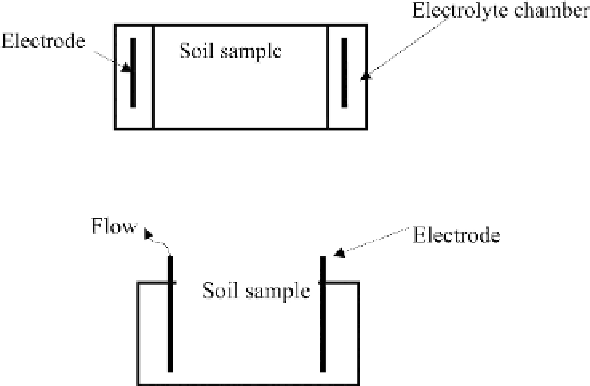
Figure 7.10
Schematic diagram of electroosmotic cell (Type I).
Figure 7.11
Schematic diagram of electroosmotic cell (Type II).
the researchers have used for their experiments. Some limitations and advantages of
this cell are as follows:
1. It is hard to transfer the undisturbed soil samples into this cell.
2. The potential gradient is relatively uniform along the cell.
3. Natural soil samples are usually prepared vertically, while electroosmotic flow is
horizontal.
Figure 7.11 shows a schematic for another setup (Type II) with the following
limitations and advantages:
1.
It is similar to field electroosmotic flow.
2.
The potential gradient is less uniform relative to Type I
3.
The analytical and experimental results may be less accurate in comparison with
the previous cell.
A series of electroosmotic consolidation experiments were carried out on an
organic soil in Malaysia (Kaniraj and Huong, 2008) ). Commercially available EVD
was used to induce electroosmosis and drainage of pore water. They concluded that
electroosmosis using EVDs was effective in the electrokinetic treatment of organic soil
(Kaniraj et al, 2011; Kaniraj and Yee, 2011) (Figure 7.12).
Kaniraj and Yee (2011) reported that electroosmotic consolidation improved the
undrained shear strength of organic soil (Figure 7.13).