Geoscience Reference
In-Depth Information
Voltage wave
Current wave
270°
360°
0°
90°
180°
Time
axis
FIGURE 11.58
Voltage and current waves in phase.
E
2
E
1
90°
Time
0°
90°
180°
270°
360°
Time
one
Time
two
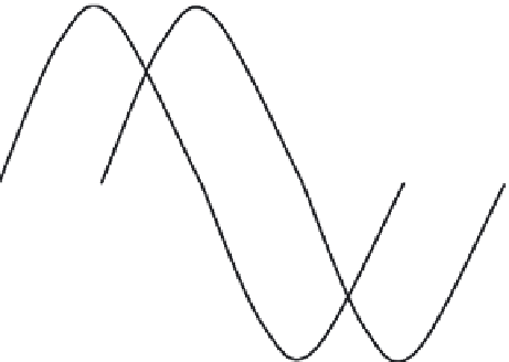
FIGURE 11.59
Voltage waves 90° out of phase.
Note:
It is important to remember that Ohm's law for DC circuits is applicable to AC circuits with
resistance only.
Voltage waves are not always in phase. Figure 11.59 shows a voltage wave (
E
1
) considered to start
at 0° (time 1). As voltage wave
E
1
reaches its positive peak, a second voltage wave (
E
2
) begins to rise
(time 2). Because these waves do not pass through their maximum and minimum points at the same
instant of time, a
phase difference
exists between the two waves. The two waves are said to be
out
of phase
. For the two waves in Figure 11.59, this phase difference is 90°.
11.7.11.11 Pha se Relationships
In the preceding section, we discussed the important concepts of
in phase
and
phase difference
.
Another important phase concept is
phase angle
. The phase angle between two waveforms of the
same frequency is the angular difference at a given instant of time. As an example, the phase angle
between waves B and A (see Figure 11.60) is 90°. Take the instant of time at 90°. The horizontal axis
is shown in angular units of time. Wave B begins at maximum value and reduces to 0 value at 90°,
whereas wave A begins at 0 and increases to maximum value at 90°. Wave B reaches its maximum
value 90° ahead of wave A, so wave B leads wave A by 90° (and wave A lags wave B by 90°). This
90° phase angle between waves B and A is maintained throughout the complete cycle and all suc-
cessive cycles. At any instant of time, wave B has the value that wave A will have 90° later. Wave B
is a cosine wave because it is displaced 90° from wave A, which is a sine wave.


Search WWH ::

Custom Search