Geoscience Reference
In-Depth Information
+
E
b
R
1
R
2
-
Path 2
Path 1
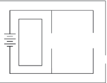
FIGURE 11.38
Basic parallel circuit.
11.7.7.1 Parallel Circuit Characteristics
A parallel circuit is defined as a circuit having two or more components connected across the
same voltage source (see Figure 11.38). Recall that a series circuit has only one path for current
flow. As additional loads (resistors, etc.) are added to the circuit, the total resistance increases and
the total current decreases. This is
not
the case in a parallel circuit. In a parallel circuit, each load
(or branch) is connected directly across the voltage source. In Figure 11.38, commencing at the
voltage source (
E
b
) and tracing counterclockwise around the circuit, two complete and separate
paths can be identified in which current can flow. One path is traced from the source through
resistance
R
1
and back to the source, the other from the source through resistance
R
2
and back to
the source.
11.7.7.2 Voltage in Parallel Circuits
Recall that in a series circuit the source voltage divides proportionately across each resistor in the
circuit. In a parallel circuit (see Figure 11.38), the same voltage is present across all of the resistors
of a parallel group. This voltage is equal to the applied voltage (
E
b
) and can be expressed in equa-
tion form as
E
b
=
E
R
1
=
E
R
2
=
E
Rn
(11.31)
We can verify Equation 11.31 by taking voltage measurements across the resistors of a parallel cir-
cuit, as illustrated in Figure 11.39. Notice that each voltmeter indicates the same amount of voltage;
that is, the voltage across each resistor is the same as the applied voltage.
Note:
In a parallel circuit, the voltage remains the same throughout the circuit.
+
E
b
v
v
v
R
2
R
1
10 v
10 v
10 v
-
FIGURE 11.39
Voltage comparison in a parallel circuit.


Search WWH ::

Custom Search