Geoscience Reference
In-Depth Information
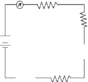
R
1
R
2
+
-
R
3
R
5
R
4
FIGURE 11.29
Current in a series circuit.
Note:
In a series circuit, the same current flows in every part of the circuit. Do
not
add the currents
in each part of the circuit to obtain
I
.
11.7.6.3 Series Circuit Voltage
The
voltage drop
across the resistor in the basic circuit is the total voltage across the circuit and is
equal to the applied voltage. The total voltage across a series circuit is also equal to the applied volt-
age but consists of the sum of two or more individual voltage drops. This statement can be proven by
an examination of the circuit shown in Figure 11.29. In this circuit, a source potential (
E
T
) of 30 volts
is impressed across a series circuit consisting of two 6-ohm resistors. The total resistance (Figure
11.30) of the circuit is equal to the sum of the two individual resistances, or 12 ohms. Using Ohm's
law, the circuit current may be calculated as follows:
E
R
30
12
T
T
I
===
2.5 amps
Because we know that the value of the resistors is 6 ohms each, and the current through the resis-
tors is 2.5 amp, we can calculate the voltage drops across the resistors. The voltage (
E
1
) across
R
1
is, therefore,
R
1
6 ohms
+
E
T
30 volts
-
R
2
6 ohms
FIGURE 11.30
Calculating total resistance in a series circuit.


Search WWH ::

Custom Search