Geoscience Reference
In-Depth Information
+
-
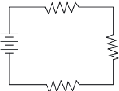
FIGURE 11.26
Series circuit.
11.7.6 s
eries
dC C
irCuit
C
haraCteristiCs
As previously mentioned, an electric circuit is made up of a voltage source, the necessary con-
necting conductors, and the effective load. If the circuit is arranged so the electrons have only
one
possible path, the circuit is a
series circuit
. A series circuit, then, is defined as a circuit that contains
only one path for current flow. Figure 11.26 shows a series circuit having several loads (resistors).
Key Point:
A series circuit is a circuit having only one path for the current to flow along.
11.7.6.1 Series Circuit Resistance
To follow its electrical path, the current in a series circuit must flow through resistors inserted in the
circuit (see Figure 11.27); thus, each additional resistor offers added resistance. In a series circuit,
the
total circuit resistance
(
R
T
) is equal to the sum of the individual resistances, or
R
T
=
R
1
+
R
2
+
R
3
+ … +
R
n
(11.26)
where
R
T
= Total resistance (Ω).
R
1
,
R
2
,
R
3
= Resistance in series (Ω).
R
n
= Any number of additional resistors in the series.
■
EXAMPLE 11.26
Problem:
Three resistors of 10 ohms, 12 ohms, and 25 ohms are connected in series across a battery
whose emf is 110 volts (Figure 11.27). What is the total resistance?
R
1
10 ohms
+
R
2
12 ohms
-
R
3
25 ohms
FIGURE 11.27
Solving for total resistance in a series circuit.


Search WWH ::

Custom Search