Geoscience Reference
In-Depth Information
+
+
Battery
Resistor (R)
Battery
Resistor (R)
-
-
Switch open
Fuse
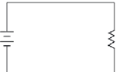
FIGURE 11.18
Open circuit.
FIGURE 11.19
Simple fused circuit.
part of the load. For simplicity, however, we usually think of the connecting wiring as having no
resistance, as it would be tedious to assign a very low resistance value to the wires every time we
wanted to solve a problem. Control devices might be switches, variable resistors, circuit breakers,
fuses, or relays.
A complete pathway for current flow, or closed circuit (Figure 11.17), is an unbroken path for
current from the emf, through a load, and back to the source. A circuit is open (see Figure 11.18) if
a break in the circuit (e.g., open switch) does not provide a complete path for current.
Key Point:
Current flows from the negative (-) terminal of the battery, shown in Figures 11.17 and
11.18, through the load to the positive (+) battery terminal and then continues through the battery
from the positive (+) terminal to the negative (-) terminal. As long as this pathway is unbroken, it
is a closed circuit and current will flow; however, if the path is broken at
any
point, it becomes an
open circuit and no current flows.
To protect a circuit, a fuse is placed directly in the circuit (see Figure 11.19). A fuse will open
the circuit whenever a dangerously large current begins to flow (i.e., when a short circuit condition
occurs caused by an accidental connection between two points in a circuit offering very little resis-
tance). A fuse will permit currents smaller than the fuse value to flow but will melt and therefore
break or open the circuit if a larger current flows.
11.7.2.1 Schematic Representation
The simple circuits shown in Figures 11.17, 11.18, and 11.19 are displayed in schematic form. A
schematic diagram
(usually shortened to “schematic”) is a simplified drawing that represents the
electrical, not the physical, situation in a circuit. The symbols used in schematic diagrams are the
electrician's shorthand; they make the diagrams easier to draw and easier to understand. Consider
the symbol used to represent a battery power supply (see Figure 11.20). The symbol is rather
simple and straightforward but is very important; for example, by convention, the shorter line in
the symbol for a battery represents the negative terminal. It is important to remember this, because
it is sometimes necessary to note the direction of current flow, which is from negative to positive,
when examining a schematic. The battery symbol shown in Figure 11.20 has a single cell, so only
one short and one long line are used. The number of lines used to represent a battery vary (and
they are not necessarily equivalent to the number of cells), but they are always in pairs, with long
and short lines alternating. In the circuit shown in Figure 11.19, the current would flow in a
coun-
terclockwise
direction—that is, opposite the direction that the hands of a clock move. If the long
and short lines of the battery symbol (symbol shown in Figure 11.20) were reversed, the current in
the circuit shown in Figure 11.19 would flow
clockwise
—that is, in the direction that the hands of
a clock move.
+
-
FIGURE 11.20
Schematic symbol for a battery.


Search WWH ::

Custom Search