Geoscience Reference
In-Depth Information
It is important to notice the distinction between the two length scales:
-
L
1
is a relevant flow path, connecting the location of maximum pressure to the
drained border.
-
L
2
is the hydraulic radius, related to the drainage capacity (volume and drained
surface).
In the operator
'
one may recognise these length scales. The gradient
is
related to the flow path
L
1
and the divergence
is related to the hydraulic radius
L
2
. For proper estimation of the hydrodynamic period in situations of multi-
dimensional consolidation problems, the determination of
L
1
and
L
2
is crucial and
requires some experience. Shortening both length scales by using vertical drains,
properly placed, a soft soil may consolidate much faster. In the one-dimensional
oedometer test both lengths are equal to the sample height
h
, and from here the
quadratic rule for scaling the consolidation period by the square of the layer
thickness originates. In multi-dimensional situations the drainage capacity
L
2
and
the characteristic seepage length
L
1
are not necessarily equal.
The simple method represents a powerful tool for the estimation of the general
behaviour of the consolidation process in any specific situation, while taking care
of boundary and initial conditions in a consistent way.
'
E
METHOD OF THE TRANSIENT LEAKAGE FACTOR
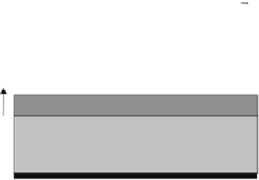
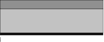
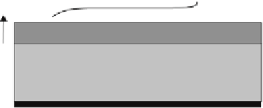
In deltas the common soil stratification consists of permeable sand layers
(aquifers) and semi-permeable clay layers (aquitards). In the case where the system
contains one aquifer and one aquitard, it is referred to as semi-confined aquifer (Fig
6.5a). The aquitard contributes to the groundwater flow in the aquifer by leakage,
which for steady situations is determined by the leakage factor
(
kDC
), where
kD
is the aquifer transmissivity (horizontal permeability times height) and
C = d/k'
the hydraulic resistance of the aquitard (height over vertical permeability). In
unsteady situations the leakage is affected by consolidation in the aquitard and
storage in the aquifer. Unsteady situations occur in pumping tests and under dikes
and embankments during temporary high water levels. An elegant method to
account for unsteady effects is the transient leakage factor (Barends).
=
1
1
z
z
h
h
h
t
/
t
/
t
t
t
0
0
0.4
1.0
0.4
1.0
B
B
B
x
x
x
t
t
t
z
z
z
d
d
d
d
d
d
Sc
v
/k'd
Sc
v
/k'd
aquitard
aquitard
aquitard
aquitard
aquitard
aquitard
q
0
q
0
q
0
q
0
q
0
q
0
aquifer
aquifer
aquifer
aquifer
aquifer
aquifer
D
D
D
D
D
D
c
v
t/d
2
c
v
t/d
2
0
0
x
x
x
1
1
2
2
(a) semi-confined aquifer system (b) the transient leakage factor
Figure 6.5 a semi-confined aquifer


Search WWH ::

Custom Search