Geoscience Reference
In-Depth Information
the deflections and bending moments will be reduced. The horizontal thrust
P
B
at
the wall tip is to be included in the analysis. Then, the system needs an additional
condition, which is, suggested by Blum, zero-displacement at the wall top. In case
of groundwater pressures, earth pressures should be determined by considering
effective soil stresses, and the groundwater pressure are included in the equilibrium
analysis, separately.
In the previously discussed design method the theory of earth pressures related
to the limit state (active and passive zones) has been applied, but in certain zones
the displacement required to develop these horizontal earth pressures may not be
realistic, and lower or higher pressures may occur. User-friendly and well-tested
numerical calculation models are available that incorporate these effects and allow
to make a proper design, covering different construction stages.
The anchorage system is an important aspect of the construction, and several
systems are in use, such as a row of piles, a pile supported cap, grouted ground
anchor, or an anchor plate or block (dead man), all equipped with tension rods or
cables. It is important to locate anchors outside failure zones, as indicated by the
dashed line (Fig 11.7b). The maximum anchor force is determined by evaluating
the passive and active thrusts on the anchor plate. To avoid anchor-rod elongation
effects, pretension may be applied. For the safety one usually applies a safety
factor of 2.0.
C
SLURRY WALLS
A slurry wall is a technique used to build reinforced-
concrete walls in areas of soft earth close to open water or
with a high groundwater table. This technique is typically
used to build diaphragm (water-blocking) walls surrounding
tunnels and open excavations, and to lay foundations
(building pits). A trench is excavated to create a form for
each wall. The trench is kept full of heavy slurry at all times.
The slurry prevents the trench from collapsing by providing
outward pressure which balances the ground pressures and
prevents water flow into the trench. Reinforcement is then
lowered in and the trench is filled with concrete, while
displacing the slurry.
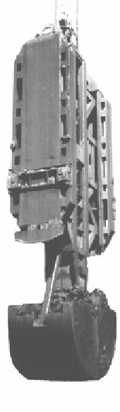
Excavation is done using a special clamshell-shaped
digger (Fig 11.8) or a hydromill trench cutter. The excavator
digs down to the design depth for the first cut. The excavator
is then lifted and moved along a trench guide wall to
continue the trench with successive cuts as needed. Once a
particular length is reached, a reinforcing cage is lowered
into the slurry-filled pit and the pit is filled with concrete
from the bottom up using tremor pipes. The concrete
displaces the bentonite slurry, which is pumped out and
recycled. It is possible to incorporate H-beams or other
structural steel elements into the freshly mixed soil, in
accordance with requirements of the excavation. On
Figure 11.8 Digger

Search WWH ::

Custom Search