Geoscience Reference
In-Depth Information
lines. This is typically accomplished by installing
new drain lines between the older ones. By keep-
ing the older drain lines intact, less new drainage
pipe is needed, thereby substantially reducing
costs to farmers. However, before this approach
can be attempted, the older drain lines need to be
located.
Finding buried drainage pipe is not an easy
task, especially for drain lines installed more than
a generation ago. Often, records have been lost,
and the only outward appearance of the subsur-
face drainage system is a single pipe outlet extend-
ing into a water conveyance channel. From this,
little can be deduced about the network pattern
used in drainage pipe placement. Without records
that show precise locations, finding a drain line
with heavy trenching equipment causes pipe dam-
age requiring costly repairs, and the alternative
of using a handheld tile probe rod is extremely
tedious at best. Zucker and Brown (1998) indicate
that satellite or airborne remote sensing technologies show some promise, but these methods are
only applicable during certain times of the year and under limited site conditions.
Consequently, there is definitely a need to find better ways of effectively and efficiently locating
buried agricultural drainage pipe. Ground-penetrating radar (GPR) may provide the solution to this
problem. Promising results have been achieved using GPR to find buried plastic and metal utility
pipelines (Hayakawa and Kawanaka, 1998; LaFaleche et al., 1991; Wensink et al., 1991). However,
to date, investigation of GPR drainage pipe detection capabilities has been limited, especially for
the Midwest U.S. Chow and Rees (1989) demonstrated the use of GPR to locate subsurface agri-
cultural drainage pipes in the Maritime Provinces of Canada, and Boniak et al. (2002) showed that
GPR could be employed to find drainage pipe beneath golf course greens. Allred et al. (2004, 2005)
evaluated GPR drainage pipe detection within agricultural field settings typical of the Midwest U.S.
The results obtained by Allred et al. (2004, 2005) regarding impacts of antenna frequency, soil
hydologic conditions, pipe construction material, and drain line orientation on GPR drainage pipe
detection are summarized within this case history along with an assessment of overall GPR drain-
age pipe detection effectiveness based on data collected at fourteen test plots throughout Ohio.
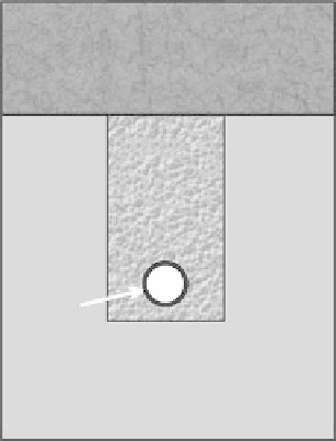
Surface tilled zone
Trench
backfill
Drainage
pipe
Undisturbed soil
fIGURe 29.1
The drainage pipe position within
the soil profile.
29.2 MAteRIAlS And MethodS
The GPR method has been described in detail in Chapter 7 of this topic. To summarize, the GPR
method involves directing an electromagnetic radio energy (radar) pulse into the subsurface, fol-
lowed by measurement of the elapsed time taken by the signal as it travels downward from the
transmitting antenna, partially reflects off a buried feature, and is eventually returned to the surface,
where it is picked up by a receiving antenna. Reflections from different depths produce a signal
trace, which is a function of returning radar wave amplitude (and hence, energy) versus two-way
travel time. Antenna frequency and factors influencing soil electrical conductivity, such as shallow
hydrologic conditions, clay content, and salinity, all have a substantial influence on the distance
beneath the surface to which the radar signal penetrates. The nature of the dielectric constant dif-
ference across a discontinuity governs the radar reflection coefficient (see Chapter 7), which, in
turn, determines the amount of reflected radar energy returning to the surface. For this study, these
discontinuities include those interfaces between with the soil material surrounding the drainage
pipe, the drainage pipe, and the air and water inside the drainage pipe.