Geoscience Reference
In-Depth Information
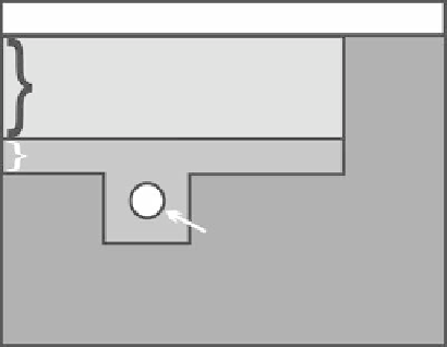
Ground surface
0.3 m Sand
0.1 m Gravel
0.1 m Diameter
drainage pipe
Native soil
fIGURe 28.1
A U.S. Golf Association (USGA) Method green.
For either the USGA Method green or California Method green, rectangular or herringbone
patterns are typically used for placement of the drainage pipe system. With the rectangular pattern,
the drainage pipe laterals merge with the main conveyance pipe at an angle of 90 degrees. With the
herringbone pattern, the drainage pipe laterals merge with the main conveyance pipe at an angle
less than 90 degrees. The spacing distance between the drainage pipe laterals within a green is usu-
ally between 3 and 5 m (Boniak et al., 2002).
Ground-penetrating radar (GPR) has the potential to provide valuable information on con-
structed soil layer thicknesses and depths and buried drainage pipe positions within a golf course
green environment. However, to date, there has been very little research conducted on golf course
applications of GPR. Boniak et al. (2002) tested GPR at two golf course greens in southern Illinois,
and were successful in mapping subsurface features (soil layers and drainage pipes) using a system
with 400 MHz center frequency antennas. In this same study, a GPR system with 900 MHz center
frequency antennas was also tested but without success due to high signal attenuation that was
attributed to recent fertilizer application. A feasibility study by Allred et al. (2005) found GPR
antenna center frequencies of 250, 500, and 1000 MHz to work equally well for mapping subsur-
face drainage pipe systems on a golf course tee and two golf course greens. For producing GPR
profiles showing constructed soil layer thicknesses and depths and drainage pipe positions, 900 and
1000 MHz center frequency antennas provided the best data (Allred et al., 2005).
Because of the time and effort devoted to the upkeep of greens, detailed information on fea-
tures beneath a green's surface will undoubtedly be helpful to the golf course superintendents and
architects involved with green maintenance and remodeling activities. When original design plans
have been lost, which is often the case, or for the purpose of quality control after new construction,
a nondestructive technique such as GPR may be the most viable alternative for determining the
thicknesses and depths of constructed soil layers or drainage pipe locations within a golf course
green environment. Using GPR to its fullest advantage in this regard requires careful attention to
computer-processing procedures and the field survey setup. Consequently, this study had two goals:
first to determine the appropriate computer-processing procedures for generating GPR profiles or
time-slice amplitude maps of golf course greens, and second, to establish the most effective opera-
tional setup for collecting GPR data on a golf course green.
28.2 MAteRIAlS And MethodS
The GPR method has been described in detail within Chapter 7 of this topic. To summarize, the
GPR method involves directing an electromagnetic radio energy (radar) pulse into the subsurface,
followed by measurement of the elapsed time taken by the signal as it travels downward from