Geoscience Reference
In-Depth Information
-
0
+
-
0
+
(a)
(b)
fIGURe 26.1
(a) Example reflected waveform that is digitized over time (increasing depth). Gain is ramped
considerably with return time (depth), to expand the amplitude of the waveform's finale such that the peak-to-
peak cycles are accentuated. (b) Waveform dances erratically when passing over saturated soil.
A
B
C
Static
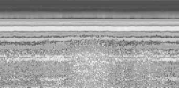
fIGURe 26.2
Radargram taken along the top of a 4 m high levee illustrating its saturated and leakage
region “STATIC” where horizons “A” is the well-drained upper profile along the levee crown, “B” the drying
front within the levee, and “C” the original soil surface prior to levee construction.
continuous soil horizon boundaries, and inverted hyperbolic-shaped curves for buried point objects
such as pipes and rocks.
An electromagnetic impulse will partially reflect off any sharp boundary separating differing
dielectric properties. The sharper the dielectric contrast, the sharper the “echo.” Within soil and
bedrock strata, a fraction of the impulse's energy will continue downward to be reflected off subse-
quent dielectric boundaries. All of the reflections ensuing from a single impulse will compose the
echoed waveform (Figure 26.1). The travel time of each returning waveform cycle (peak-to-peak)
is a function of the reflector depth and the overall dielectric of the transmission media. Naturally,
the resulting waveform's signal strength will exponentially degrade with depth (or increasing return
time) due to this repetitive echoing process as less of the impulse's energy progresses into deeper
strata, until the tail of the returning waveform is completely absorbed at some depth range by soil
conductivity. Therefore, considerable ramped gain must be applied to the returning waveform. If the
depth range is extended beyond the antenna's normal probing capability for the site's soil conditions,
static will uniformly appear within the lower extents of the radargram because only background
noise is being amplified.
26.1.1 R
a d a R g R a M
c
h a R a c t e R i s t i c s
o f
s
a t u R a t e d
s
o i l
A thin layer of perched moisture atop a distinct textural boundary of two soil horizons offers a
highly reflective plane, which is easily identifiable within the radargram as dry soil has a much
lower dielectric constant than wet soil. Due to this interface, GPR is an excellent tool for soil hori-
zon profiling. Furthermore, a sharp dielectric interface is also supplied by a rapidly progressing