Geoscience Reference
In-Depth Information
March 9, 2001
CMP 24(10.7, 9.7)
May 22, 2001
CMP 5(10.7, 9.7)
Antenna separation (m)
Antenna separation (m)
0
2
4
6
8
10
0
2
4
6
8
10
0
0
50
50
100
100
150
150
(a)
(b)
Sept 18, 2001
CMP 19(10.7, 9.7)
January 09, 2002
CMP 14(10.7, 9.7)
Antenna separation (m)
Antenna separation (m)
0
2
4
6
8
10
0
2
4
6
8
10
0
0
50
50
100
100
150
150
(c)
(d)
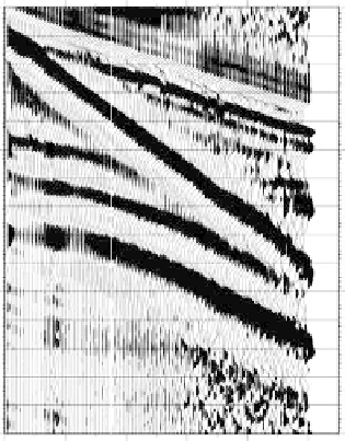
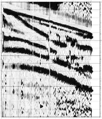
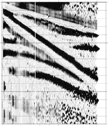
fIGURe 23.2
Common midpoint (CMP) surveys from the same location. The CMPs were acquired in
(a) March, (b) May, (c) September, and (d) January. Note the changes in the ground wave and reflection char-
acter from March to January. The vertical white line in each plot shows the optimal antenna separation.
The second step acquires the wide-offset reflection (WOR) data. These profiles are denoted as
WOR profiles because the offset between the antennas is much wider than is usually used in stan-
dard GPR reflection profiles. The method uses an optimal antenna separation derived from CMP
surveys to reliably identify the air wave and the direct ground arrival times.