Geoscience Reference
In-Depth Information
SV
R
P
I
SV
I
SV
R
P
R
β
SV
I
P
R
β
P
I
V
P
1
,
V
S
1
, ρ
1
Layer 1
Layer 2
V
P
1
,
V
S
1
, ρ
1
Layer 1
Layer 2
V
P
2
,
V
S
2
, ρ
2
V
P
2
,
V
S
2
, ρ
2
P
T
P
T
SV
T
SV
T
(a)
(b)
SH
R
SH
I
β
SH
I
V
S
1
, ρ
1
V
S
2
, ρ
2
Layer 1
Layer 2
SH
T
(c)
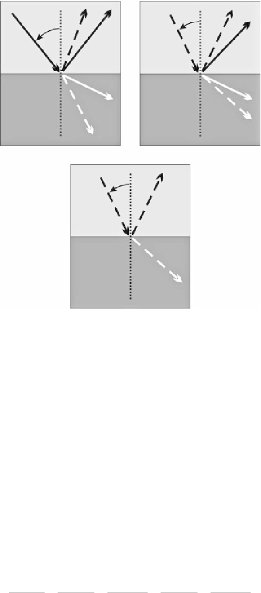
fIGURe 8.8
Body wave transformations at a subsurface interface separating two layers having different
seismic velocities (
V
P
and
V
S
) and density (ρ) properties: (a) incident P-wave, (b) incident SV-wave, and (c) inci-
dent SH-wave.
and S-wave velocities (
V
P
2
and
V
S
2
, respectively) are greater than the Layer 1 P-wave and S-wave
velocities (
V
P
1
and
V
S
1
, respectively). The Layer 1 density is ρ
1
, and the density of Layer 2 is ρ
2
. As
shown in Figure 8.8a, for β
P
I
> 0, a P-wave initially traveling through Layer 1 and incident at the
interface (P
I
) will generate a P-wave reflected back through Layer 1 (P
R
), an SV-wave reflected back
through Layer 1 (SV
R
), a P-wave transmitted into Layer 2 (PT),
T
), and an SV-wave transmitted into
Layer 2 (SV
T
). An incident SV-wave (SVT).
I
), assuming β
SV
I
> 0, likewise produces PT,
R
, SV
R
, P
T
, and
SV
T
(Figure 8.8b). However, as depicted in Figure 8.8c, an incident SH-wave (SH
I
) generates only
reflected SH-waves (SHT).
R
) and transmitted SH-waves (SHT).
T
).
The travel directions of the reflected and transmitted seismic waves in Figure 8.8 are given as an
angle referenced to an imaginary line extending through and oriented perpendicular to the interface
(dotted vertical lines in Figure 8.8) and can be determined by Snell's law based only on the incident
seismic wave angle and the seismic velocities of the two layers adjacent to the interface. For an
incident P-wave, Snell's law gives:
()
=
()
=
( )
=
1
(()
=
( )
V
sin
β
sin
β
sin
β
sin
β
sin β
P
P
SV
P
SV
I
R
R
T
T
(8.4)
V
V
V
V
P
P
1
S
1
P
2
S
2