Geoscience Reference
In-Depth Information
Transmit loop
Receive loop
Primary
signal
Secondary
signal
Secondary
eddy currents
Object causing
secondary field
(a) Primary field from transmit loop, and
secondary field caused by conductive object
Primary field
Secondary field
Time
Time
Phase
1 cycle
(a) Primary and secondary fields
arriving at the receive antenna
(c) Amplitude, time, phase relationships
of 1 cycle of oscillation of the primary signal
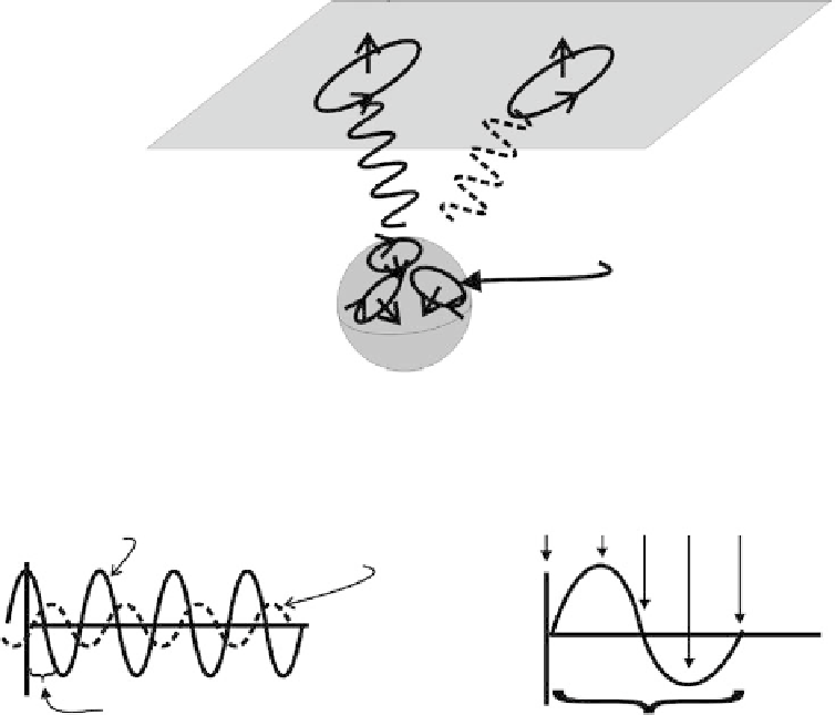
fIGURe 6.4
The primary and secondary electomagnetic field: (a) the received signal referenced to the pri-
mary field, and (b) the amplitude and phase of the received signal related to several descriptions of the field. A
single cycle representing a continuously oscillating frequency domain wave for a single point on the spreading
primary field and the induced secondary field is shown.
meaningful only when it is related to some standard time reference, which is usually the primary
field. For example, a secondary field that is 90°
out of phase with the primary field has its maximum
amplitude (or zero crossings) shifted one-quarter cycle in time with respect to the primary field. A
phase shift of 180° means the secondary field is the mirror image of the primary field. The relative
phase measurement points on the primary wave are shown in Figure 6.4c.
The field measured at the receiver is the vector sum of the primary and the secondary fields, as
shown in Figure 6.5. The electric and magnetic fields are three-dimensional vectors with a magnitude
and direction that vary with each cycle of the combined primary and secondary fields measured at
the receiver. At any location away from the source, the tips of the electric and magnetic field vectors
can be viewed as tracing out ellipsoids in space over a period of time, as shown in Figure 6.5a. The
tracing of the ellipsoid is repeated for each new cycle of each frequency of the transmitted wave.
The size of the ellipsoid at any point on its surface is proportional to the magnitude of the electric
(or magnetic) field vector at that particular point. This can be called a polarization ellipsoid. There
is a minimum and maximum value of the ellipsoid that can be measured at any point. Furthermore,
the ellipsoid can be tilted in space, with the angle of the major axis oriented at an angle that is a
function of the position and electrical properties of the object in the subsurface.