Geoscience Reference
In-Depth Information
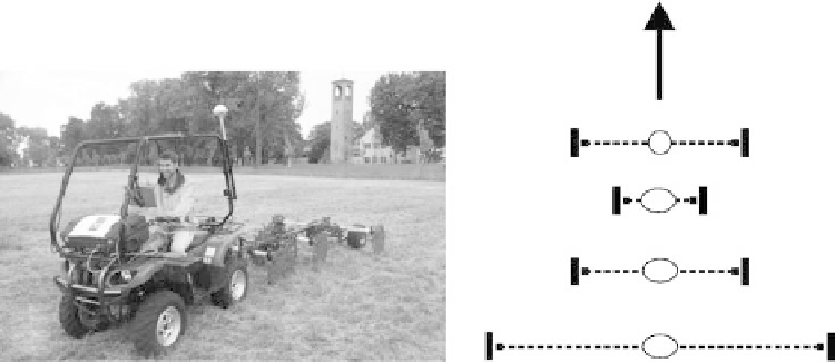
Direction
of Travel
C
I
C
P
P
∆
V
P
∆
V
P
P
∆
V
P
(Not to Scale)
(a)
(b)
fIGURe 5.7
Geocarta ARP-03: (a) photo of system in operation, and (b) plan view of electrode arrangement
(
C
= current electrode,
P
= potential electrode). (Courtesy of Geocarta SA, Paris, France.)
electrode array configurations (Figure 5.6c). The shorter Wenner array (0.7 m) maps the top 0.3 m
of the soil profile, and a longer one (2.1 m) maps the top 0.9 m of the soil profile. As indicated by
Figure 5.6a and Figure 5.6b, these electrode arrays are oriented perpendicular to the direction of
travel while ρ
a
is being measured.
The first galvanic contact continuous resistivity measurement systems were probably developed
in France (Dabas et al., 1994). The ARP-03 (Figure 5.7a) is one of these systems and is marketed by
Geocarta SA. This system is integrated with a GPS receiver for accurate determination of ρ
a
mea-
surement locations. A radar triggered ρ
a
measurement is obtained for every 0.2 m of travel. Steel
coulters serve as electrodes for the ARP-03. To improve ground contact, metal spike extensions
are attached along the outer circumference of the coulter electrodes. The plan view arrangement of
the ARP-03 electrodes is depicted in Figure 5.7b. As shown, there is one pair of current electrodes
and three pairs of potential electrodes. The arrangement shown in Figure 5.7b provides for three
electrode arrays (one current electrode pair and one potential electrode pair), with each array hav-
ing a trapezoidal configuration. Investigation depths for the three ARP-03 electrode arrays are 0.5,
1, and 2 m.
5.8.2 c
a P a c i t i v e l y
c
o u P l e d
R
e s i s t i v i t y
Capacitively coupled systems are also capable of collecting continuous resistivity measurements.
As the name implies, these systems use a capacitive-coupling approach to introduce electric current
into the ground and to measure potential differences at the soil surface. This capacitive-coupling is
accomplished using coaxial cables. Essentially, a large capacitor is formed by the coaxial cable and
the soil surface. The metal shield of the coaxial cable is one of the capacitor plates, and the soil sur-
face is the other capacitor plate, with the outer insulation of the coaxial cable acting as the dielectric
material separating the two plates. The system transmitter applies an alternating current (AC) to the
coaxial cable side of the capacitor, in turn generating AC in the soil on the other side of the capaci-
tor. With regard to the receiver, a similar phenomenon occurs, except in reverse. The AC in the soil
charges up the capacitance of the coaxial cable, which is measured to determine the potential dif-
ference (voltage) generated by the flow of electric current within the soil.
Two coaxial cables are attached to the transmitter, one on each side, to form a current dipole.
Two coaxial cables are also attached to the receiver, one on each side, to form a potential dipole.
This equipment setup, along with some initial data processing, allows a capacitively coupled system
to mimic a conventional galvanic contact dipole-dipole electrode array having one pair of current