Geoscience Reference
In-Depth Information
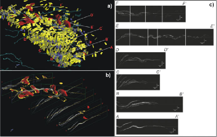
Fig. 1.8 3-D Structural Field Interpolation (SFI) modeling example from Hillier et al. (
2013
).
View of data set and SFI cross sections.
Yellow
and
blue
sides of tablets indicate stratigraphic tops
and bottoms. Semi-transparent
red
domes and
yellow
fringe surface represent previously
interpreted Archean basement granitic gneiss domes with unconformably overlying Paleopro-
terozoic Dewar Lakes Formation quartzites depicted in
yellow
around margins of dunes (de Kemp
and St-Onge
2007
). (a) Perspective view of dip data (tablets), location of cross-sections, hydrog-
raphy and previously interpreted basement domes. (b) Perspective view of cross-sections with dip
measurements and SFI calculation results on all Sections. (c) Vertical sections shown on regional
map (Fig.
1.7
) and 3-D views Figs.
1.8a, c
, with data and STI models projected from 1 km normal
to section. Structural form lines of SH are in white. Apparent dip measurements depicted as
oriented lines, input parameters used for the calculation were: IDW exponent
¼
2, type of
neighborhood
¼
ellipsoidal oriented north-south, number of nearest neighbors used
¼
25, formline
step length
¼
100 m, total formline length
¼
30 km (Source: Hillier et al.
2013
, Fig. 9)
As a strategy it is therefore wise to first model the geometry of the layers and then to
“simplify the geological equation” by removing the influence of that geometry. One
can go about this by defining, mathematically, a new space where all horizons are
horizontal planes and where faults, if any, have been eliminated. If the layers are
folded, one can use a curvilinear coordinate system (
u
,
v
,
t
) with the (
u
,
v
)axes
parallel to the layering and the
t
-axis orthogonal to the layers. In geomodeling, Mallet
(
2002
) introduced the “geological space” (G-space) with such a curvilinear coordinate
system. Examples in physical geologywhere choosing a curvilinear coordinate system
is appropriate include the following: (1) Equations of flow through porous media in
reservoir engineering become greatly simplified with a curvilinear coordinate system
(
u
,
v
,
t
)with(
u
,
v
) defining the iso-pressure surfaces and the
t
-axis aligned with the
streamlines; and (2) propagation of seismic front waves in the subsurface also is
simplified if one chooses a 3-D curvilinear coordinate system (
u
,
v
,
t
)where(
u
,
v
)
matches the seismic front with
t
corresponding to the ray paths (see, e.g., Mallet
2002
).
Search WWH ::

Custom Search