Geoscience Reference
In-Depth Information
velocity boundary layer to that where the thermal bound-
ary layer thickness affects the heat transfer occurs at a
point where the theoretically derived hydrostatic
(
Pr
)
1
/
2
layer becomes thicker than the
E
1
/
3
Stewartson layer.
With this, we can now state the principle of the Prandtl
number dependent coupling between the boundary layer
and the baroclinic waves:
1. The horizontal temperature profile across the entire
domain is characterized by high-temperature gradients
within the thermal boundary layers and smaller gradients
outside of them.
2. The velocity behavior is split into velocity bound-
ary layers and the “fluid interior.” The interior is defined
by the horizontal velocities and is therefore terminated
by the
E
1
/
3
Stewartson layers.
3. The effective forcing of the thermal wind in the
fluid interior is determined by the horizontal temperature
difference across the fluid interior.
4. Therefore the temperature at the top of the
E
1
/
3
Stewartson layers determines the thermal wind. The ratio
of the effective temperature contrast over the imposed
temperature contrast as a function of the Prandtl number
for axisymmetric flow derived from MORALS results is
shown in Figure 3.11.
5. Finite-amplitude baroclinic waves, at least those
with a wave number preferred by Hide's geometric con-
straint, i.e., equation (3.3), tend to fill the gap up to the
edges of the Stewartson layers.
6. Finite-amplitude waves enhance the heat transfer
through the interior and thereby act to reduce the tem-
perature gradient within the fluid interior.
7. If the thermal boundary layers are thinner than
the Stewartson layers, the temperature at the edges are
10
1
10
0
10
−1
10
−2
10
−1
10
0
10
2
10
1
Pr
1/4
E
1/3
Pr)
1/2
(
Θ
E
1/2
(
Pr)
−1/4
V
= jet
E
Θ
W
= 0
T
= −1/2
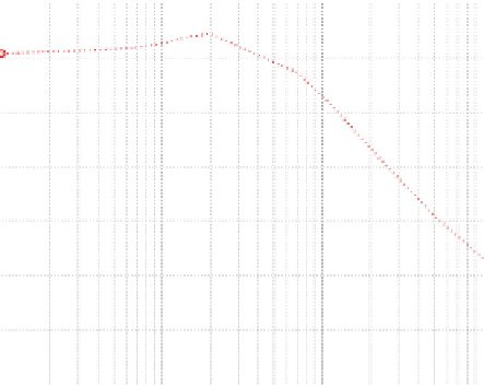
Figure 3.10.
Comparison of boundary layer thicknesses
obtained from axisymmetric solutions of the MORALS code
with the theoretical Stewartson layer thicknesses and thermal
layer thicknesses against Prandtl number. The thickness variable
is scaled against the
E
1
/
3
Stewartson layer.
computed boundary layer thicknesses at the inner cold
wall. There the theoretical two Stewartson layers are
shown as the horizontal dashed lines and the location of
the maximum jet velocity in the interior is shown as the
solid line, while the outer hydrostatic thermal boundary
layer is the dash-dotted line and the inner buoyancy layer
is the dashed line. The extent of interior baroclinic flow is
measured as the location of the maximum velocity of the
baroclinic jet. This is located just outside the outer
E
1
/
4
Stewartson layer and did not appear to depend on the
Prandtl number at all. Since the axisymmetric solutions
always showed a strong downwelling at the cold sidewall
adjacent to a small upwelling (and vice versa at the warm
wall), the extent of the vertical flow is measured as the
location of zero vertical velocity and shown as the trian-
gles with the dotted line. This is clearly limited by the inner
E
1
/
3
Stewartson layer. To obtain a measure of the ther-
mal boundary layer, the distance from the wall where the
temperature had increased from
0.6
0.5
0.4
0.3
0.2
T/
4rel-
ative to the mean temperature was found. This is shown
by the crosses and dotted line. For Pr
−
T/
2to
−
0.1
2 this thermal
layer has a constant thickness that appears to be limited
by the vertical convection since it is very close to the edge
of the velocity boundary layer. Once the Prandtl number
increases beyond Pr
0
10
−1
10
0
10
1
10
2
Pr
2, the temperature gradient near
the walls increases noticeably and follows a decay similar
to that of the buoyancy boundary layer. The changeover
from a solution where the heat transfer is limited by the
∼
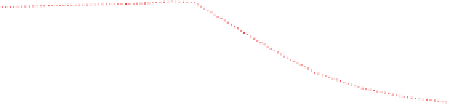
Figure 3.11.
Effective temperature contrast across the fluid
interior against Prandtl number obtained from axisymmetric
solutions of the MORALS code.