Geoscience Reference
In-Depth Information
Table 14.2.
Dynamical parameters of various laboratory experiments on rotating wakes.
Experiments
α
δ
Ro
I
N/f
Bu
Re
Boyer and Davies
(1982) 1- 6 1 0.02-0.4 0 — 50-200
Boyer and Kmetz
(1983) 0.4-1.8 1 0.3-3.5 0 — 65-2300
Boyer et al.
(1984) 0.6-3 1 1.4-4 0 — 2500-37,500
Tabouriech and Renouard
(1996) 10 1 3-10 0 — 10,000
Stegner et al.
(2005) 4-14 1 0.3-4 0 — 150-1400
Perret et al.
(2006) 0.5 0.13 0.06-0.35 0 0.1-10 200-1000
Teinturier et al.
(2010) 0.2 0.1-0.15 0.4-4 4-6 0.5-1.5 4000-30,000
Stegner et al.
(2012) 0.15-0.6 0.1-0.15 0.3-3.5 7-14 4-70 2500-45,000
When the experiment is done in a single homogeneous fluid layer, the layer thickness ratio is set to
un
ity. If this homogeneous
layer has a free surface, we can use the layer thickness
h
to define a barotropic Rossby radius
R
d
=
gh/f
and the corresponding
Burger number Bu =
(
2
R
d
/D)
2
. When there is no stratification, we fix the stratification parameter to zero,
N/f
=0.
could be thinner and not impacted by a strong bot-
tom Ekman pumping. According to standard asymptotic
expansion, the vertical acceleration will be negligible if
α
2
Ro
(a)
Ω
0
1[
Stegner
, 2007], hence for experimental con-
figurations where
α
U
0
0.1 the hydrostatic balance will be
satified even for finite Rossby number Ro
1 as for the
oceanic flows. Another geometric parameter, the vertical
aspect ratio
δ
=
h/(h
+
H)
, is also crucial. For the latter a
close similarity could be achieved between the open ocean
and the laboratory where
δ
h
(b)
0.1.
There are various ways to control the island Rossby
number in rotating experiments. The relative velocity
U
0
,
the size of the cylinder
D
, or the turntable rotation
0
=
f /
2 could be varied to satisfy the similarity with oceanic
values from Ro
I
=0.1toRo
I
= 10. Several experimen-
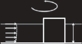
tal setups were used to generate a vortex street (Figure
14.2) and control the size of the eddies and their intensity.
The first experimental investigations on rotating wakes
[
Boyer and Davies
, 1982;
Boyer et al.
, 1984;
Tarbouriech
and Renouard
, 1996] were made with a fixed cylinder while
the mean speed
U
0
of the upstream current was regu-
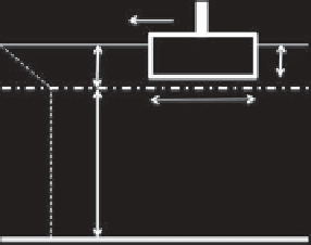
lated by a hydraulic pump (Figure 14.2a). However, it
could be easier to perform PIV (particle image velocime-
try) measurements with a top-view camera if the fluid
layer is at rest, on the rotating turntable, and the cylinder
is translated at a constant speed (Figure 14.2b). Such con-
figurations with high-resolution PIV measurements were
used in recent experiments [
Stegner et al.
, 2005;
Perret
et al.
, 2006b;
Teinturier et al.
, 2010;
Lazar et al.
, 2013b],
especially when the rotating fluid layer is stratified (Figure
14.2c).
In order to mimic the oceanic density stratification of
the thermocline, a salt stratification is preferentially used
in the laboratory. A two-layer stratification which sup-
ports both baroclinic and barotropic motion could be
used in a first step to mimic the upper themocline [
Perret
et al.
, 2006b]. In order to satisfy a small vertical aspect
U
0
h
c
(c)
U
0
ρ
(
z
)
h
c
h
D
H
Figure 14.2.
Various experimental setups used to generate a
vortex wake in a rotating fluid layer: (a) homogeneous current
impinging a fixed cylinder, (b) homogenous layer at rest with a
drifting cylinder, and (c) stratified layers with a drifting cylinder
confined in the upper layer.
ratio (
δ
0.1), the light upper layer is much thin-
ner than the deep lower one. Thus, the baro
clin
ic Rossby
radius can be approximated by
R
d
g
∗
h/f
,where
g
∗
=
g(ρ
2
−
ρ
1
)/ρ
2
is the reduced gravity. The densities