Geoscience Reference
In-Depth Information
resonate with Rossby modes in the upper layer with
c
≈
in Figure 6.10b corresponds to the first Poincaré mode
in the upper layer resonating with a Rossby wave in
the lower layer. The pressure and velocity fields for
this mode are plotted in Figure 6.11c, and confirm this
interpretation. Note that the same instability appears
at higher
k
for Poincaré modes of higher order with
decreasing growth rates (Figure 6.10c). This is the RP
instability.
A new dispersion curve
kc
= 1 denoted by
I
in the
Figures 6.10b and 6.10c also appears. It corresponds to
inertial motion in the lower layer, with the quiescent upper
layer. The absence of pressure variations is typical for
inertial oscillations. This mode was already discussed by
Paldor and Ghil
[1991] and
Gula et al.
[2010]. In spite
of intersections of this curve with other branches of the
dispersion diagram, no resonances and hence no instabil-
ities between the inertial motion and other modes arise
due to its pressureless character. Indeed, pressure fluc-
tuations are required for the instability to arise [
Cairns
,
−
U
0
. This is the standard mechanism of the baroclinic
instability, as explained in the previous section, which
occurs for wave numbers
kR
d
<
1. The corresponding
pressure and velocity fields in both layers are plotted in
Figure 6.11a. Both fields are typical of a Rossby mode.
Rossby modes in the lower layer can also resonate with
the frontal mode in the upper layer (RF interaction). The
frontal mode has the characteristics of a Rossby wave for
low wave numbers, and the unstable mode under consid-
eration is therefore very similar to the classical baroclinic
instability (RR). The corresponding pressure and velocity
fields in both layers are plotted in Figure 6.11b.
For higher Rossby and Burger numbers (Figures 6.10b
and 6.10c), the Rossby-Rossby interaction is not allowed
anymore as the horizontal extension of the surface cur-
rent is too small compared to the Rossby deformation
radius. The RF mode is the primary unstable mode
with wave numbers
kR
d
≈
0.5
÷
1. The second instability
(a)
10
10
10
5
5
5
0
0
0
-5
-5
-5
-10
-10
-10
-10
-5
0
5
10
-10
-5
0
5
10
-10
-5
0
5
10
(b)
4
4
4
3
3
3
2
2
2
1
1
1
0
0
0
-1
-1
-1
-2
-2
-2
-3
-3
-3
-4
-4
-4
-4
-3
-2
-1
0
1
2
3
4
-4
-3
-2
-1
0
1
2
3
4
-4
-3
-2
-1
0
1
2
3
4
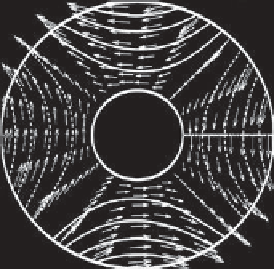
Figure 6.11.
Pressure and velocity fields of the upper (left) and lower (middle) layers and interface height (right) of (a) the unstable
RR mode for Ro = 0.02 and
k
=5(
kR
d
= 0.6, see Figure 6.10a), (b) the unstable Rossby-frontal (RF) mode for Ro = 0.2 and
k
=2
(
kR
d
= 0.6, see Figure 6.10b),