Geoscience Reference
In-Depth Information
(a)
(b)
3
z
z
H
c
4
X
null
X
X
H
m
N
null
2α
N
α
1
x
2
x
Ω
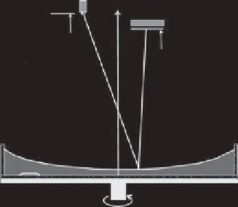
Figure 5.1.
(a) Experimental setup and (b) geometry of the reflection from the perturbed surface. In (a) the numbers refer to (1),
rotating tank (2) mountain for experiments with bottom topography, (3) photo/video camera, and (4) light source with color mask.
In (b) the angle
α
is the angle between the normal to the surface at null point
N
null
and the normal to the perturbed surface
N
.
plane (
x
,
y
). The two components of the slope of
η
are
color coded and the images of the surface obtained by
this method are color maps of the surface. They show the
flows of different scales, including small/mesoscale eddies,
gravity and inertial waves, and global scale currents and
Rossby waves. We call this laboratory technique altimetric
imaging velocimetry because it allows us not only to visu-
alize the flow field but also to calculate the velocity field
from measured slopes. Before we describe the conversion
of the slopes into velocities, we give in what follows some
more technical details of AIV.
Figure 5.1a shows a sketch of a typical experimental
setup. A video or photo camera observes from above the
reflection of light from the free surface of the fluid. The
light source is also located above the water and contains
a color mask, where the color varies in two directions
across the mask. The mask resembles a color wheel used
by painters. A rainbow of bright saturated colors con-
verges toward the center where the color mix results in a
grayish tone. Thus each point of the mask is character-
ized by a unique color that can be measured using three
indices. The images are usually coded in values of red,
green, and blue (RGB) color. It is convenient to convert
the RGB color into a so-called
Luv
color space where the
first index
L
stands for lightness and
u
and
v
denote chro-
maticity values. Ultimately, only two indices are required
to code the color in the
x
and
y
directions across the mask
such that we can ignore the lightness. This also makes this
method less vulnerable to errors due to the variation of
lightness/brightness across the experimental images.
The AIV has evolved from the (gray-scale) optical
altimetry introduced by
Rhines et al.
[2007] by incorpo-
rating color coding. The principle of optical altimetry can
be briefly described as follows. If a paraboloidal surface
is illuminated by a light source of small but finite size
located at a height of about twice the focal length of the
paraboloid and slightly off the axis of rotation, the surface
appears to be lit almost uniformly when observed from
a certain distance and angle. Under these conditions (see
below) any point of the surface observed by the camera
adjacent to the light source corresponds to a small area
(point) of the light source. When the surface is perturbed,
the slopes of the surface elevation field change the angles
of reflection. As a result an observer sees different areas
of the light source. If there is a gradient of brightness
across the surface of the light source such as that which
occurs naturally in the light bulb, which is always brighter
in the center where the filament is, the entire (perturbed)
surface of water will be visualized by variations of inten-
sity. When, instead of a light bulb a color mask is used,
the observer will see the reflections of the different areas
of the mask.
The optical setup is simple and in fact does not require
any optical elements since the parabolic surface of the
rotating fluid is used as if it were a mirror in a Newtonian
telescope. The setup can include an inexpensive video or
photo camera and can be used in a teaching laboratory. A
more specialized camera that does not use color compres-
sion is necessary when more accurate results are required
for research purposes.
Using the reflection law of optics, we can describe
the path of the ray originating from a certain point at
the mask (
X
,
Y
) reflecting from the point (
x
,
y
)atthe
surface of water and coming to the camera. The ray paths
can be calculated using the vector reflection law:
R
=
I
−
2
(
I
·
N
)
N
(5.8)
where
R
and
I
are reflected and incident unit vectors and
N
is the normal to the surface. The vectors can be written
as follows: