Geoscience Reference
In-Depth Information
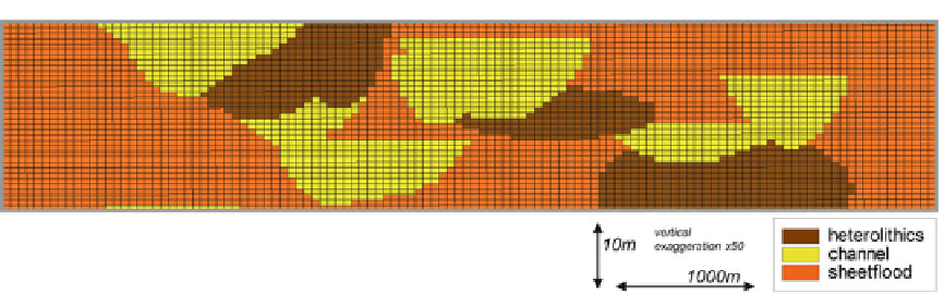
Fig. 2.33
Cross section through the 'Moray Field'
model, an outcrop-based model through Triassic fluvial
clastics in NE Scotland. Figures
2.35
,
2.36
,
2.38
and
2.39
follow the same section line through the models and each
model is conditioned to the same well data, differing only
in the selection of rock modelling algorithm
The algorithms work by selecting objects
from the prescribed distribution and then
rejecting objects which do not satisfy the well
constraints (in statistics, the 'prior model'). For
example, a channel object which does not inter-
sect an observed channel in a well is rejected.
This process continues iteratively until an
acceptable match is reached, constrained by the
expected total volume fraction of the object, e.g.
30 % channels. Objects that do not intersect the
wells are also simulated if needed to achieve the
specified element proportions. However, spatial
trends of element abundance or changing body
thickness are not automatically honoured because
most algorithms assume stationarity (no interwell
trends). Erosional, or intersection, rules are
applied so that an object with highest priority can
replace previously simulated objects (Fig.
2.33
).
There are issues of concern with object
modelling which require user control and aware-
ness of the algorithm limitations. Firstly, it is
important to appreciate that the algorithm can gen-
erate bodies that cross multiple wells if intervals of
the requisite element appear at the right depth
intervals in the well. That is, the algorithm can
generate probabilistic correlations without user
guidance - something that may or may not be
desirable. Some algorithms allow the user to con-
trol multiple well intersections of the same object
but this is not yet commonplace.
Secondly, the distribution of objects at the
wells does not influence the distribution of
inter-well objects because of the assumption of
stationarity in the algorithm. Channel
morphologies are particularly hard to control
because trend maps only affect the location of
the control point for the channel object and not
the rest of the body, which generally extends
throughout the model. A key issue with object
modelling, therefore, is that things can easily go
awry in the inter-well area. Figure
2.34
shows an
example of 'funnelling', in which the algorithm
has found it difficult to position channel bodies
without hitting wells with no channel
observations; the channels have therefore been
preferentially funnelled into the inter-well area.
Again, some intuitive geological sense is
required to control and if necessary reject
model outcomes. The issue illustrated in
Fig.
2.34
can easily be exposed by making a net
sand map of the interval and looking for bulls-
eyes around the wells.
Thirdly, the element proportions of the final
model do
not
necessarily give guidance as to the
quality of the model. Many users compare the
element ('facies') proportions of the model with
those seen in the wells as a quantitative check on
the result, but matching the well intersections is
the main statistical objective of the algorithm so
there is a circular logic to this type of QC. The
key thing to check is the degree of 'well match'
and
the spatial distributions
and
the total element
proportions (together). Repeated mismatches or
anomalous patterns point
to inconsistencies
between wells,
geometries
and
element
proportions.