Geoscience Reference
In-Depth Information
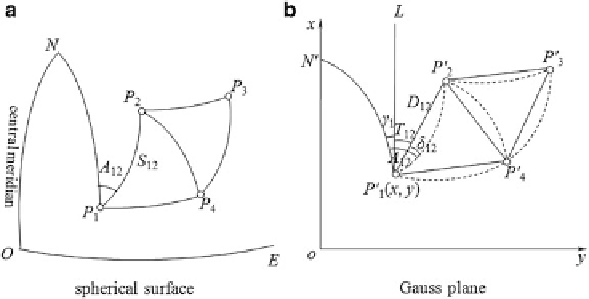
Fig. 6.11 Gauss projection of geodetic network from a spherical surface (a) to a plane (b). Dashed
lines indicate projection of the sides of the triangles
Grid Convergence (Meridian Convergence)
The angular difference between grid north and true north is known as the grid
convergence, denoted by
. The grid convergence is measured from the projected
meridian to the vertical grid lines, positive in the clockwise direction and negative
in the anticlockwise direction.
In Fig.
6.11
we assume that a geodetic network P
1
P
2
P
3
P
4
...
ʳ
is on the ellipsoid.
The geodetic coordinates of the initial point P
1
is (L
1
, B
1
). Length of the initial side
P
1
P
2
(geodesic distance) is S
1.2
. The initial geodetic azimuth is A
1.2
. The observed
values are those of the directions of each side of the triangulation network. After
Gauss projection, the central meridian ON is projected as the axis of ordinates, i.e.,
the x-axis. The equator OE is projected as the axis of abscissas, i.e., the y-axis. The
geodetic network P
1
P
2
P
3
P
4
... is projected as P
1
0
P
2
0
P
3
0
P
4
0
... on the plane.
According to the direct solution of the Gauss projection, all meridians, parallels,
and geodesics are projected as curves except the central meridian and equator.
Hence, the sides of the triangle formed by connecting geodesics on the ellipsoid are
projected as the corresponding curves (expressed by dashed lines in Fig.
6.11
). The
meridian P
1
N that passes through P
1
is P
1
0
N
0
after projection, namely the direction
of true north. A line P
1
0
L drawn through P
1
0
parallel to the x-axis is the direction of
grid north.
As a Gauss projection is conformal, the angles of a triangle on the ellipsoid will
remain unchanged after being projected. Therefore, the angles constituted by the
dashed lines on the Gauss plane are equal to the corresponding angles on the
ellipsoid. The geodesics generally appear as curves rather than straight lines in
the projection (i.e., the dashed lines in Fig.
6.11
). To satisfy the needs of compu-
tations on the plane, one first needs to replace curves with chords that connect
different points (represented by solid lines in Fig.
6.11
). It is therefore necessary to
Search WWH ::

Custom Search