Geoscience Reference
In-Depth Information
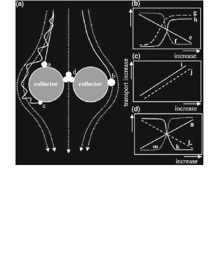
Fig. 12.25 Schematic diagrams for transport of engineered nanoparticles (NPs) in porous media.
The filtration mechanisms are illustrated in (a), modified from Elimelech et al. (
1995
), whereas
the influences of properties of NPs, collectors, and solution condition on the transport are
presented in (b, c), and (d), respectively. The black spheres, dotted lines, and thick lines in
(a) stand for NPs, the fluid streamlines, and the particle path (trajectory), respectively. The NPs
can attach to the collector through (a) gravitational sedimentation, (b) interception, and
(c) Brownian diffusion. (d) Large aggregates may be physically retained by small pores.
Transport of NPs through the porous media (normally negatively charged) decreases with
increasing (e) size, and (f) zeta potential of the NPs. The transport increases with increasing
surface hydrophilicity of (g) the NPs and (h) coating of dispersants. The transport increases with
increasing (i) size of the collectors, and (j) porosity of the media. The transport decreases
with increasing (k) ionic strength, and (l) temperature of the fluid solution and increases with
increasing (m) natural organic matter content of the fluid, and (n) fluid velocity (Lin et al.
2010
)
the soil column relatively quickly, and after one pore volume reached the maxi-
mum eluting concentration. This ''faster than conservative tracer'' transport was
explained by preferential flow of the AgNPs due to size exclusion and electrostatic
repulsion of the negatively charged AgNPs from the soil aggregates. This expla-
nation was further supported by comparison with the transport of AgNPs and
tracer (bromide) in the same soil, as well as AgNP transport in a sand column, as
shown in Fig.
12.26
b. In both cases, the transport exhibited classical behavior,
with no retention of the bromide in soil or the AgNPs in sand; the transport rate is
indicated by C/C
0
= 0.5 for 1 pore volume.