Geoscience Reference
In-Depth Information
3
(a)
(b)
2
Beam Incident
1
0
No beam
0
20
40
60
80
200
0.2
40
30
100
0.1
20
10
0
0
Discharge Current
0
20
40
60
80
Charge Voltage
Time[ s]
Time [
µ
s]
µ
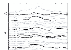
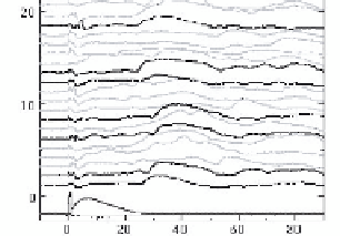
Fig. 5. Experimental result of rotation angle of propagating beam's polarization plane.
(a) Differential outputs of 40 times discharge event, (b) validation of differential output
and discharge current.
was
>
0.94. This result was in agreement with the result of the simulation,
which showed that the rotation of the polarization plane had the same time
response as the discharge current.
The rotation angle of the polarization plane was estimated from the
measured results. Considering the amplification of the differential amplifier
(
100), the intensity ratio of the mutually orthogonal polarization outputs
was 1.00:0.98. Therefore, the rotation angle
δ
is calculated as
×
√
1
.
00
−
√
0
.
98
√
1
.
00 +
√
0
.
98
=0
.
29 (deg
.
)
tan
−
1
(
√
0
.
98
/
√
1
.
00) = tan
−
1
δ
=
π
4
−
This value also agreed with the result of the simulation.
The correspondence between the obtained signal with the discharge
current showed that the propagating beam interacted with the discharge
only at a single optical path. Larger rotation angle could be obtained
by increasing the discharge current and gap length. Since the discharge
chamber used in this study can only accommodate discharge gaps of about
10 cm, the same experiment will be performed in open air, using discharge
gaps in the order of 1 m and a larger impulse voltage generator.