Geoscience Reference
In-Depth Information
z
a
b
B
0
z
′
z
r
2
ʸ
0
y
′
ʸ
n
y
1
x
˕
0
y
x
x
′
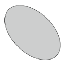
Fig. 10.5
Schematic plot of a cracked zone model. (
a
) The general reference frame and a local
frame associated with the crack. (
b
) General scenario.
1
—the cracked zone,
2
—a ground-based
recording station. Taken from Surkov and Hayakawa (
2006
)
where
a
is the mean value of
A
1
,
b
Dr
a
and the vector
h
u
s
i D h
u
.
r
;
1
/
i
is
defined as the static/residual displacements in the medium. These displacements are
assumed to be maximal inside the cracked zone and they should gradually decline
in the surrounding rock.
As one example, the displacement field for a tension crack is found in
Appendix H. A coordinate system and random orientation of the crack plane
are shown in Fig.
10.5
a. The displacement components at the observation point
depend on the random angles
0
and '
0
. For simplicity, an equal probability for
the crack plane orientation inside the cracked zone is assumed. As follows from
Eq. (
10.75
), the averaging of the displacement vector over the crack orientation
gives only the radial component. This means that the mean displacement field of
the crack ensemble is spherically symmetric at far distance from the cracked zone,
and it is not surprising since the equal probability for the vector
n
orientation is
assumed. Conversely, if the probability distribution for the crack plane orientation
is non-spherically symmetric, there must occur certain declination from Eq. (
10.75
).
For reasons of convenience, all the cracks are considered to have the same disk-
shaped form with different radius R. The displacement discontinuity/jump, Œ
u
z
,
normal to the crack surface is considered as a given function of time. The static
value of the discontinuity (at t
!1
) is supposed to be proportional to the crack
length l
D
2R, so that Œ
u
z
D
kl where k
D
0:001-0:01.
As has already been stated, the attenuation of acoustic waves due to dissipation
and absorption of the acoustic energy in actual rocks may greatly affect the
magnitude of both the acoustic waves and the GMPs. In order to estimate this
effect we introduce the acoustic damping factor T
a
.r;R/
D
exp .
r=L.R//, which
depends on the distance r and the crack radius. Multiplying Eq. (
10.75
)bythis
factor, taking into account Eq. (
10.58
) and above expression for Œ
u
z
, we obtain
r
2
exp
and
u
0
D
1
;
kl
3
4
4
w
2
3
u
0
r
L.R/
h
u
r
iD
(10.15)


Search WWH ::

Custom Search