Geoscience Reference
In-Depth Information
peculiarities of the electrical properties of the rocks at
different depths and to build the corresponding geo-
logical model.
The prospection with direct current is widely
applied and very useful for determination of the
anisotropic characteristics of the rocks. The karstified
rocks are, as rule, bad conductors of electricity.
Geological processes as faulting, dissolution, shear-
ing, jointing, weathering, and alteration can increase
the fluid permeability of the rocks and contribute to
the formation of patterns of lower electrical resistiv-
ity. In this case, the minerals of the karstified rocks
are practically insulators and the electrical conduction
is due to the electrolytes (groundwater, wet clayey
substance, etc.) filling the pore space and the fissures.
If the fractures or the underground karst galleries are
without electrically conductive filling (air), these
inhomogeneities will have higher (infinite) electrical
resistivity relatively to the rock's matrix.
The measurements by direct electrical current can
be performed using point or dipole sources. The dis-
position of the electrodes on the ground determines
the geometrical type of the array. The most common
disposition of the electrodes is shown in Fig.
2.11
.
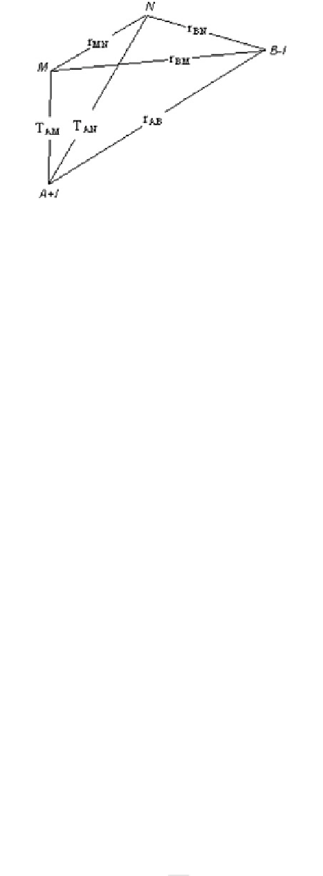
The aim is to measure the potential difference
DU between the electrodes M and N when a direct
current I is applied between the electrodes A and B.If
the resistance between opposite faces of the con-
ducting body with length L and uniform cross-sec-
tional area S is R, the resistivity q in homogenous
material from single point source is:
Fig. 2.11
Four electrodes array AMNB. A and B are the
current electrodes (C
1
and C
2
in some textbooks), and M and
N (respectively P
1
and P
2
) are the electrodes measuring the
potential difference
q
¼
U
M
U
N
I
AB
2pr
:
ð
2
:
2
:
4
Þ
The potentials in points M and N are the sums of the
potentials from the current electrodes A and B, the
electrical current being +I and -I, respectively:
U
M
¼
U
M
þ
U
M
¼
q
I
1
r
AM
q
I
2p
1
r
BM
2p
ð
2
:
2
:
5
Þ
U
N
¼
U
N
þ
U
N
¼
q
I
1
r
AN
q
I
2p
1
r
BN
:
2p
So, the resistivity for uniform homogenous volume in
the upper hemisphere is:
q
¼
DU
MN
I
AB
2p
:
ð
2
:
2
:
6
Þ
r
AM
1
1
r
BM
1
r
AN
þ
1
r
BN
q
¼
S
R
L
:
ð
2
:
2
:
1
Þ
The relative disposition of the electrodes deter-
mine the so-called ''coefficient of the array''—k:
The resistivity SI unit is ohm meter (Xm).
When electrical current I is applied, and the mea-
sured potential difference is DU, then the relationship
with the electrical resistance R is given by Ohm's law:
2p
k
¼
:
ð
2
:
2
:
7
Þ
r
AM
1
1
r
AN
1
r
BM
þ
1
r
BN
Practically, at meso- and macro-level, the rocks are
neither uniform, nor homogenous. At given position
between the electrodes, the electrical current passes
trough composite rock material with imposed sec-
ondary brittle or ductile deformations. This fact
argues the use of the term ''apparent resistivity'' q
a
for the measured in situ resistivity. The final equita-
tion becomes:
DU
¼
R
I
:
ð
2
:
2
:
2
Þ
Using
Eq. (
2.2.1
)
the
above
relationship
can
be
written, as follows:
q
¼
DU
I
S
L
:
ð
2
:
2
:
3
Þ
At a distance r, away from the source electrode
(A or B), the hemisphere has a surface area S = 2pr
2
,
so if L = r, and DU
MN
= U
M
- U
N
:
q
a
¼
k
DU
I
:
ð
2
:
2
:
8
Þ