Information Technology Reference
In-Depth Information
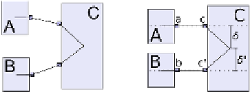
Fig. 4.
In the new port model, two
proper nodes may be connected to the
same side of another via ports, as in
(a). The systematic use of
offset align-
ments
between port nodes and their
parents, i. e., constraints of the form
y
ʴ
(
p
)
+
ʴ
=
y
ˀ
(
p
)
,
ʴ
=0asshownin(b),
creates a risk of node-edge and node-
node overlaps far exceeding what was
anticipated with the original ACA algo-
rithm, as could have occurred here had
node
B
been as tall as node
C
,forex-
ample. We have extended ACA to prop-
erly handle such cases.
(a)
Proper nodes con-
nected via port nodes
(b)
Ports aligned by
ACA
most one proper node to be aligned with another in a given compass direction,
in our case (with ports) it will often be desirable to have more. See Fig. 4.
In order to adapt ACA to the new port model we made it possible to ignore
certain edges—namely those connecting port nodes to their parents—and also
generalised its overlap prevention methods significantly. Instead of the simple
procedure for preventing multiple alignments in a single compass direction [10],
we use the VPSC solver [5] for trial satisfaction of existing constraints, the new
potential alignment, as well as non-overlap constraints between all nodes and a
dummy node representing the potentially aligned edge.
Thus, while the ACA process continues to merely centre-align nodes—in this
case port nodes
d
∈
D
—wehavealloweditto
in effect
align several proper nodes
v
1
,...,v
k
∈
V
at port positions as in Fig. 4, meeting
the requirement R6 of data flow diagrams.
V
with a single one
u
∈
2.3 Edge Routing
We now consider node positions to be fixed, and use the methods of Wybrow et
al. [19] to route the edges orthogonally. We return from
G
to
G
, using the final
positions of the port nodes
d
∈
D
to set
routing pins
, fixed port positions on the
nodes
v
∈
V
where the edges should connect.
3 Handling Compound Graphs
Graphs containing compound nodes can be handled using several different strate-
gies. Schulze et al. employ a
bottom-up
strategy, treating every compound node
as a separate graph, starting with the inner-most nodes. This allows application
of different layout algorithms to each subgraph which reduces the size of the
layout problem, and possibly the overall execution time. They remark, however,
that the procedure can yield unsatisfying layouts since the surroundings of a
compound node are not known; see Fig. 5a for an example where two unnec-
essary crossings are created inside the
TM controllers
actor and two separate