Chemistry Reference
In-Depth Information
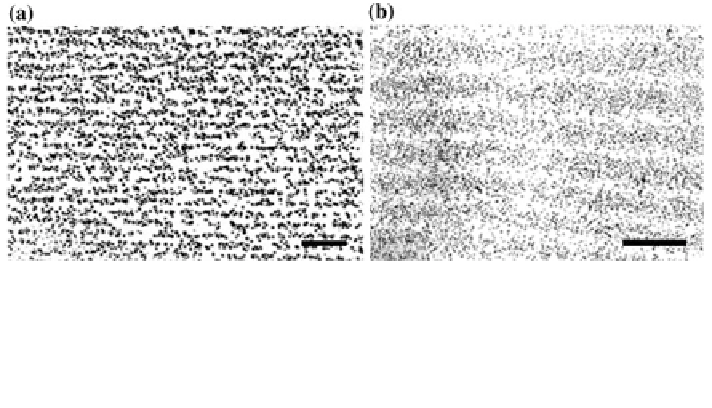
Fig. 2.2 The electron micrographs of hologram cross sections (transversal). a A Lippmann phase
hologram recorded in a Holotest 8E75HD plate using a HeNe laser operated at 632.8 nm (
50 %
diffraction ef
ciency). Reprinted with permission from [
65
]. Copyright 1988 The Optical Society
of America. b A phase hologram recorded in a Slavich PFG-03 M
film using a HeNe laser
operated at 632.8 nm. Scale bars =1
µ
m. Reprinted with permission from [
41
] Copyright 2014
The American Chemical Society
*
diffraction
field produced by the hologram [
63
]. Holographic recording changes the
optical properties of the recording material. An amplitude hologram is recorded
when the interference pattern created by the object and the reference beams is
copied as variation of the absorption coef
cient of the recording material. A phase
hologram is created when the holographic recording leads to variation of the
refractive index or the thickness of the hologram. Holographic gratings can also be
recorded in
“
”
ection holograms are typically formed
by passing an expanded beam of laser light through the recording plate to illuminate
an object on the other side of the plate. Light from the object is then re
Denisyuk
re
fl
ection mode. Re
fl
ected back
through the plate and interfered with the light passing through the plate for the first
time, thus forming standing waves of light, which are recorded as
fl
“
holographic
fringes
running roughly parallel with the plane of the recording medium [
43
,
64
]
(Fig.
2.2
). When the hologram is illuminated with a white light source, the fringes
in the recording medium act as Bragg mirrors, which diffract light monochromatic
(or narrow-band) light and serve as sensitive wavelength
”
filters. The replayed image
represents the original object used during the laser exposure. This diffracted light
from the periodic gratings results in a narrow-band spectral peak determined by the
wavelength of the laser light used and the angle between the two recording beams.
The holographic diffraction is governed by Bragg
'
is law:
k
peak
¼
2n
0
K
sin
h
ð
2
1
Þ
:
λ
peak
is the wavelength of the
where
first order diffracted light at the maximum
intensity in vacuo, n
0
is the effective index of refraction of the recording medium,
ʛ
is the spacing between the two consecutive recorded NP layers (constant
parameter), and
ʸ
is the Bragg angle determined by the recording geometry.