Image Processing Reference
In-Depth Information
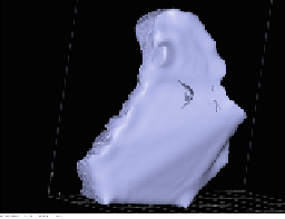
FIGURE 29
3D printing of point cloud back side view with STL size (inches)
X
= 3.94,
Y
= 5.24,
Z
= 6.41.
Imperfections are apparent in all of the 3D printings. There are holes in the neck area be-
cause there is so litle information in that area being given to the printer. The thickness of
the material used for printing, some kind of plastic inserted as cartridges in the 3D printer is
greater than the depth information given by the point cloud in this region. The nose height is
greater than the original object yielding a shape that is more pointed and not as round. That
could have been introduced by the software for point cloud to 3D model conversion because
this does not show up in previous renderings of the object.
7 Summary and conclusions
A new phase-unwrapping method, called binary code patern unwrapping, was introduced
and illustrated within a reconstruction system based on digital fringe projection. Along the
way, practical issues had to be overcome and these and their solutions were enumerated. The
fringe projection method, of which phase unwrapping is one step, was illustrated by showing
the results obtained at the end of each stage of the process. The unwrapping method impacts
results of later steps and binary code patern unwrapping was found to produce a more accur-
ate point cloud of the object in both depth and width directions compared with the previously
studied multiwavelength unwrapping, but with tradeofs.
In binary code patern unwrapping, at least three shifted fringe paterns should be projected
on the object. The projected fringe paterns should also have 120° phase diference. According
to our practical results, the camera and projector should be close to each other, and the camera
and projector optic axes should be parallel to the reference plane axis. Considering the men-
tioned optical calibration and system seting, three pictures should be taken from the object
while the fringe paterns are projected on it. Next, the phase of the assorted paterns should be
calculated. This process will be repeated with and without the presence of the object. In fact,
it has been shown that the depth properties of the object can actually be calculated using the
subtraction results of the object phase and the reference plane phase.
The main contributions reported here to ongoing research are as follows:
• Implementation and creation of practical parameterized experimental tools based on the-
ories in the fringe projection method
• The development of a new phase-shifting process that reduces the number of pictures in
fringe projection method
• Illustration that, by reducing the size of the fringe paterns, the level of preciseness of both
height and details of the 3D model will increase
• Investigation of the optical arrangement of the fringe projection method and illustration by
example of how failure in optical arrangement may cause failure in the whole method.
Search WWH ::

Custom Search