Image Processing Reference
In-Depth Information
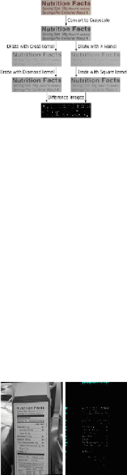
Figure 5
demonstrates the dilate-erode algorithm used on an image segment that contains
text. The dilate steps are substantially whiter than their inputs, because the appropriate kernel
is used to expand white pixels. Then the erode steps partially reverse this whitening effect by
expanding darker pixels. The result is the pixels with the largest differences between the ori-
ginal image and the result image.
Figure 5
shows corners detected on an image segment with
text.
FIGURE 5
Corner detection for text spotting.
in the image and is horizontally or vertically aligned with the smartphone's camera. Unfor-
tunately, these conditions sometimes do not hold in the real world due to shaking hands or
failing eyesight. The exact problem that the new algorithm addresses is twofold. Does a given
input image contain a skewed NL? And, if so, within which aligned rectangular area can the
NL be localized? In this investigation, a skewed NL is one which has been rotated away from
the vertical alignment axis by up to 35-40° in either direction, i.e., left or right. An additional
objective is to decrease processing time for each frame to about 1 s.
3.2 Corner Detection and Analysis
Before the proper NL localization begins, a rotation correction step is performed to align in-
puts which may be only nearly aligned. This correction is performed by taking advantage of
high numbers of horizontal lines found within NLs. All detected lines that are horizontal with-
in 35-40° in either direction (i.e., up or down) are used to compute an average horizontal ro-
tation. This rotation is used to perform the appropriate correcting rotation. Corner detection
is executed after the rotation. The dilate-erode corner detector is applied to retrieve a two-di-
mensional bitmap where true white pixels correspond to detected corners and all other false
FIGURE 6
Visualization of the corner detection output.
Search WWH ::

Custom Search